Table of Contents
Introduction
The Border Gateway Protocol or BGP is one of the most critical networking protocols that is used today. It is said to be the Protocol of the Internet. Why? The Internet is built up of several Autonomous Systems (ASes) and BGP helps to route data packets across different AS to reach a destination. BGP uses the best path of ASes (the statement is partially true that we will see later) so that packets are routed efficiently and quickly.
Suppose, you need to access a website that is hosted in the US from India. The data packets route through different AS to reach the server in the US and the response is sent back again through different AS to reach your source location in India.
An Autonomous System (AS) is a network of several interconnecting networking devices (majorly routers) that is controlled by a single organization or ISP. Different AS combine to form what we call the Internet. There is an Autonomous System Number (ASN) that is assigned for each autonomous system. ASN uniquely identifies a specific network of a service provider. ASN is a 16-bit number between 1 and 65534 and a 32-bit number between 131072 and 4294967294. An ASN needs to be created if a network connects to more than one AS.
The Internet Assigned Numbers Authority (IANA) assigns ASNs to Regional Internet Registries (RIR) which then allocates the ASNs to service providers.
Why the name – Border Gateway Protocol?
Because the Border Gateway Protocol is popularly used between the two AS to forward data packets across them.
Example
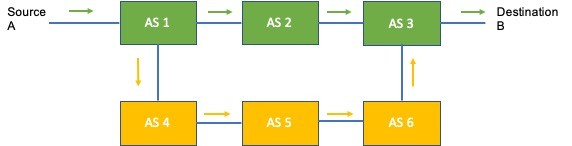
Consider the image above.
In this figure, data packets need to travel from Source A to Destination B. There are six Autonomous Systems between A and B. Considering the BGP’s working, the best path to reach destination B is using AS 1 -> AS 2 -> AS3 rather than AS 1 -> AS 4 -> AS 5 -> AS 6 -> AS 3. The first path has 3 hops while the second path has 5 hops.
This is a very simple example. The actual scenario can be very complex. In addition to the number of AS hops, there are a few other properties that help decide and forward the data packets via BGP using the best path.
For BGP to work, the proper routing information must be present within the AS. As different AS are managed by different service providers, there needs to be a contract between them so that a service provider’s AS can accept the routes from the other AS and forward the traffic. This contract often requires a fee to be paid by a service provider to the other service provider to carry their data. This means that a service provider is not bound to necessarily accept the routes from another AS.
Gateway to Gateway Protocol (GGP) and Exterior Gateway Protocol (EGP)
The very first internet protocol was Gateway to Gateway protocol or GGP. It was a distance-vector protocol i.e. protocol that worked on the count of hops and was considered to be an advanced version of RIP. The “Gateway” used here is a router.
GGP is now obsolete.
Exterior Gateway Protocol or EGP
The protocol is a predecessor of the Border Gateway Protocol (BGP). It is a distance-vector protocol and is more advanced than GGP. An important thing to note about EGP is that it only supports tree-like topology. This means that to reach a particular destination, only a single path is available.
EGP was the first protocol to use the concept of an Autonomous System (AS).
EGP is used to exchange the routing table information between the hosts which is called the reachability information. The routing table here consists of known hosts, the addresses (destinations) they can reach, and the cost of metric to reach the destination. Regular polling happens between hosts to check for any updates and accordingly, the routing tables are exchanged.
EGP does not use any metrics to determine the best path. The processing and distribution of routing information from different AS is given to a set of core gateways/routers. Thus, the distribution in EGP is centrally controlled. The job to find the best path is given to these core gateways/routers.
Because of the centrally controlled system, there are bound to be scaling issues as the number of Autonomous Systems grow. Today, a distributed system architecture is used where the processing of routes happens on each Autonomous System thereby reducing the load.
EGP uses two messages Hello and I-Heard-You (I-H-U) before the initiation of the exchange of routing information.
Before BGP, EGP version 3 or EGP3 was used for the functioning of the internet. Later RFC 1772 came that laid the foundation for the migration of EGP to BGP. Currently, BGP version 4 or BGP4 is being used as the internet protocol.
Don’t confuse exterior gateway protocols with Exterior Gateway Protocol.
Border Gateway Protocol (BGP)
The Border Gateway Protocol (BGP) is the most commonly used exterior gateway protocol or exterior routing protocol. BGP takes care of the functioning of the internet. The protocol is related to Inter-Domain Routing Protocol (IDRP) and uses a policy-based routing where the network administrator configures certain policies on the nodes and the routing is performed based on those policies. Unlike EGP where central authority is used, in BGP, the routing decisions are handled within the AS itself and the reachability information is exchanged.
The BGP can also be used as the Interior Gateway Protocol called the Internal Border Gateway Protocol or iBGP.
Routing Policies can be defined to advertise only a specific set of routes to the neighbor AS.
BGP and TCP
BGP works on top of TCP and thus reliability is ensured during the exchange of reachability information. The BGP uses TCP port 179 for the exchange of information.
By default, BGP uses the output interface of the router that is connected to the peer as the source interface for establishing TCP connections. If a BGP router has multiple links to a peer, then, when the source interface fails, BGP has to re-establish TCP connection with another interface causing network oscillation. Therefore, it is recommended to use a loopback interface as the source interface to enhance the stability of the BGP connection.
BGP is a typical example of the path vector protocol. A path vector protocol analyses the ASes based path along with the destination to produce a loop-free topology. It tells the nodes that a specific destination can be reached via the particular AS or sequence of ASes. The concept of “Speaker Nodes” is popular in the path vector protocol. Here, a specific node (Speaker Node) from each AS acts as the advertisement node and sends the full path vector information to its neighbor AS Speaker Node.
Single Homed, Dual Homed, and Multi-Homed
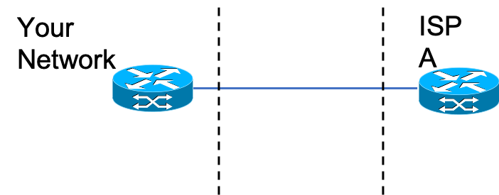
A Single Homed design in BGP means that a single connection is available from your network to an ISP. This means that there is only one exit point toward the ISP. Here, there is no need to enable BGP as there is only a single path to exchange information. The disadvantage is that there is a single point of failure or no redundancy.
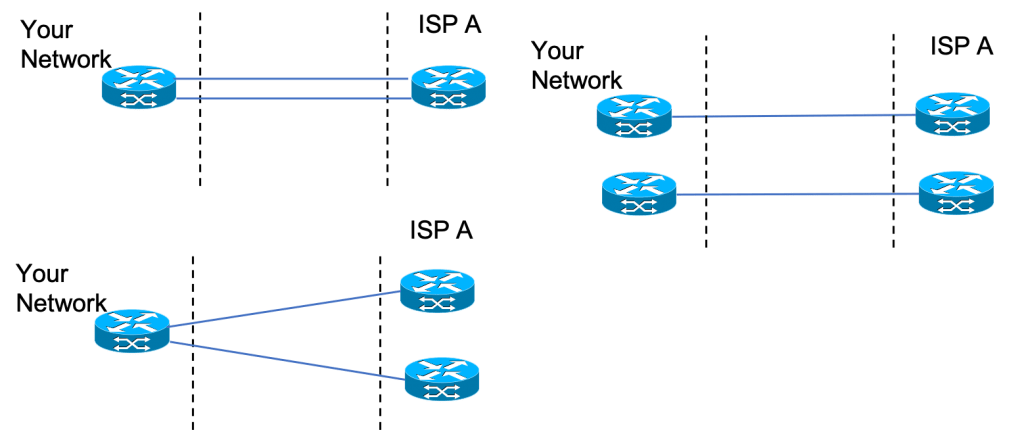
Dual Homed design in BGP refers to the configuration where there are two network connections to the same ISP. Thus, when compared with single homed, the dual homed has added redundancy. In the dual homed design, your network and ISP could be connected between the same nodes or different nodes.
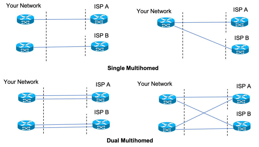
Multi-Homed design is where your network is connected to two or more AS or ISPs. BGP works best for multi-homed configuration.
Multi-Homed has two configurations: Single Multihomed and Double Multihomed.
Difference between internal and external Border Gateway Protocol
There are two flavors of BGP i.e. internal Border Gateway Protocol (iBGP) and external Border Gateway Protocol (eBGP).In the external Border Gateway Protocol, routes are exchanged between the two AS, while in the internal Border Gateway Protocol, the routes are exchanged internally within an AS. It is not necessary to enable iBGP for eBGP to work. For internal AS, many different protocols like OSPF, IS-IS, etc. can be used. iBGP and eBGP also have their own set of rules to run.
Working of Border Gateway Protocol
To initiate the exchange of routing information between the two AS, there should be edge nodes on each AS that are directly connected. These nodes are called the BGP Peer nodes. A BGP session can also be created between non-directly connected nodes (but they should be reachable from one another).
We can also enable iBGP within an AS to exchange the routing and other networking information. The iBGP flavor used within an AS in the case of L3VPN is called MP-BGP i.e. Multiprotocol BGP. It is an extension to the BGP where IPv4 (unicast and multicast) and IPv6 (unicast and multicast) address families are supported. Apart from IP, MP-BGP also supports other address families like L2 VPN, VPNv4, and VPNv6. VPNv4/v6 routes are part of L3VPN.
BGP peers initially exchange the full BGP routing tables. After this exchange, the peers send incremental updates as the routing table changes.
When a “neighbor adjacency” between the peering nodes is established and the routes are identified by the BGP, it uses its decision process to find the best route.
Border Gateway Protocol States & Messages
There are six states in the BGP setup between the peer nodes. The BGP states are Idle, Connect, Active, OpenSent, OpenConfirm, and Established. When the Established state is reached, the BGP session is established and the BGP Peers share their reachability information.
Let us discuss each of these states.
Idle State
In the Idle state, no BGP messages are exchanged. When the peers are configured for BGP, the TCP connections are initiated. A node initiates a TCP session with the peering node and also waits for the TCP connection from the peer node. The state is changed from Idle to Connect. This state is then dumped in the BGP neighbor table with the Neighbor’s IP and state.
If an error occurs, the Idle state is maintained and retry (using ConnectRetryTimer) for TCP connection is initiated. Based on the configuration, the specific count of retries takes place. The first retry happens after 60 seconds. Subsequently, the ConnectRetryTimer doubles.
Connect State
During the Connect state, a 3-way TCP handshake happens. If the ConnectRetryTimer depletes before this state is complete, a new TCP connection is attempted, the ConnectRetryTimer is reset, and the state is changed to Active. In case of any other error, the state reverts to Idle.
If the 3-way handshake is successful, the ConnectRetryTimer is reset and an OPEN message is sent to the neighbor. The state then changes to the OpenSent.
The neighbor with a higher IP address initiates and maintains the session. The initiating node may use any Source port but the destination port is always TCP 179.
Active State
If the TCP session encounters a delayed response in the Connect state, the BGP goes into the Active state. The 3-way handshake is retried. If it fails, the ConnectRetryTimer is reset and the state reverts to Connect. In case the handshake is successful, the state changes to OpenSent.
OpenSent State
This state is achieved once the TCP 3-way handshake is successful. In this state, an OPEN message has already been sent from the source node to the neighboring node and the source node is awaiting an OPEN message from the neighboring node. After the originating node receives the OPEN message from the other node, both OPEN messages are checked for errors.
The OPEN message has a Router ID (RID). This BGP Router-ID (RID) is a unique 32-bit number. It identifies the BGP router in the advertised prefixes. The RID is used as a loop prevention mechanism for routers advertised within an AS.
The following items in the OPEN message are compared:
- BGP Versions should match.
- The source IP in the OPEN message should match the IP that is configured for the neighbor.
- The ASN in the OPEN message should match the ASN for the neighbor.
- BGP Identifiers (RID) should be unique. If RID is not available, this condition will fail.
- Security Parameters (Password, TTL, etc.) are also compared.
If there are no errors in the OPEN messages and the parameters are matched, Hold Timer is negotiated and the KEEPALIVE message is sent. The state then changes to OpenConfirm. If there is an error in the OPEN message, a notification is sent to the peer node and the state reverts to Idle.
If the TCP session receives a disconnect message, the ConnectRetryTimer is reset and the state changes to Active. Any other error makes the state change to Idle.
OpenConfirm State
In this state, the source node waits for the KEEPALIVE message from the neighboring node. Once the KEEPALIVE message is received, the state changes to the Established state. In case of any error (like hold timer expires, etc.), the NOTIFICATION is sent and the state changes to Idle.
Established State
This is the final state where the BGP peers form adjacency and start exchanging the reachability information using the UPDATE messages. These UPDATE messages contain the Network Layer Reachability Information (NLRI). The hold timer is reset when UPDATE and KEEPALIVE messages are exchanged. In case the hold timer expires the state changes to Idle.
A BGP speaker sends 19-byte KEEPALIVE messages every 60 seconds to maintain the connection. BGP is unique among the routing protocols in using TCP as its transport protocol.
Summary of Border Gateway Protocol (BGP) Messages
| BGP Message | Description |
| OPEN | The message is used to exchange the connection parameters. |
| UPDATE | The message is used to exchange reachability information. Routing updates and removals are part of the message. |
| NOTIFICATION | Used to notify any error. |
| KEEPALIVE | BGP session monitoring message. |
Border Gateway Protocol Tables
Border Gateway Protocol maintains three tables. BGP table, BGP Neighbor table, and BGP Routing table.
BGP table – This table is also called the BGP Topology table. It contains the Network Layer Reachability Information (NLRI) and NLRI attributes. An NLRI is a prefix and its length (example – 204.192.23.45, /25). This table contains all the routes from the neighbors. Length here is the network mask.
BGP routers exchange Network Layer Reachability Information (NLRI). This information is an indication of the full paths that a route must take to reach the destination network. These paths are BGP ASNs.
BGP Neighbor Table – The BGP neighbor table contains the Neighbor’s IP and state.
BGP Routing Table – The BGP Routing Table (Local Routing Information Base or Loc-RIB) contains all the BGP-based Routing information. If the conditions are met, the best BGP route to a destination is added to the global IP Routing table or RIB (Routing Information Base).
The BGP also has a conceptual Adjacent Routing Information Base, Incoming (Adj-RIB-In). This stores the neighbor information with the NLRI that is sent from the neighbor. So, for each neighbor, we have an Adj-RIB-In. Similarly, there is an Adj-RIB-Out that contains the neighbor information with the NLRI to be sent to the neighbor.
The best route that goes in the Global Routing Table or RIB depends on the protocols being used. If different protocols are advertising the same prefix, the best route will be selected based on Administrative Distance (AD). The protocol that has the lowest AD is used in the RIB. The BGP has an AD of 170 for Juniper.
Border Gateway Protocol Commands
Enabling neighbor discovery (Check the sequence of commands below)
For directly connected peers –
#router bgp <ASN>
#router-id <IP Address of the source router>
#neighbor <IP Address of directly connected interface of remote router> remote-as <ASN>
For indirectly connected peers –
#neighbor <IP Address of entry interface but not directly connected> remote-as <ASN> – This command can be used in iBGP.
#network <Network IP Address> mask <Subnet Mask> – This command helps advertise the network to the peer node.
Commands to view various BGP tables
| Table Name | Command | Details |
| BGP Neighbor table | show ip bgp neighbor summary | To view the BGP neighbors. |
| BGP table | show ip bgp | Shows network, next hop to reach that network, metric, local preference, weight, path. |
| BGP Routing table | show ip route bgp | Shows all BGP routes. |
Border Gateway Protocol Decision Process
To reach a particular destination there may be many routes from a source to destination. It is thus necessary to define policies using which the most optimal path is identified. In the case of no policies, the smallest AS Path is used as also stated in the previous sections.
But, AS path is not the only decision-making factor for calculating the best route in BGP. There are other factors that give the network admins more control over selecting the best routes. Several attributes are added to the route advertisements that can be used to select the best route. The following table shows the factors that a router uses to compare the two routes. The first attribute has the highest priority, and so on.
| Attribute | Controlled by Local or Neighbor AS |
| Highest local preference | Local |
| Lowest AS path | Neighbor |
| Lowest Origin Type | NA |
| Lowest MED (Multi-exit Discriminator) | Neighbor |
| eBGP learned over iBGP learned | NA |
| Lowest IGP cost to border router | Local |
| Lowest Router ID (RID) | NA |
The higher priority attributes can be used to force the best route decision.
Route Reflectors
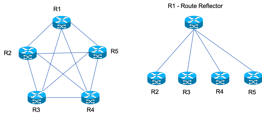
Route Reflectors are used to reduce the number of BGP sessions in a mesh network. This becomes important in iBGP where the edge nodes exchange the BGP information. Suppose there are 5 nodes, then 10 BGP peering sessions (using the formula – n * (n-1)/2; where n is the number of nodes) will need to be configured for BGP to work. This count will increase as the BGP peers will be added.
In the case of Route Reflector, a single node can be used to peer with all the nodes in the network or AS to advertise the routing information. Thus, each node will have a single connection with the Route Reflector (RR). In our example, where we had to create 10 BGP connections, using RR, we can reduce them to just 4. Thus, RR is a concentration point where all the BGP routes are stored and from where the BGP updates are sent to other nodes.
Rules for Route Reflectors
Here are some rules relating to Route Reflectors:
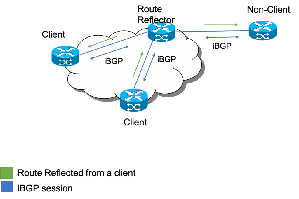
- If a route is received from a non-client peer, reflect it to clients and EBGP peers.
- If a route is received from a client peer, reflect it to all the client and non-client peers, and also to EBGP peers.
A client is a node in the cluster of nodes in which iBGP is implemented. Any node outside this cluster is a non-client.
The figure below shows an example of a client and non-client configuration. The cloud denotes the cluster. The figure also shows the reflection scenario when a route is advertised by a client.
It is important to note that if the Route Reflector fails, the BGP functionality shall get affected. Thus, it is important to create redundancy and at least two Route Reflectors should be used.
RR attaches a Cluster-ID to the advertised routes towards clients and non-clients. Cluster-ID is important to prevent routing loops.
Good Reads and References
CURATED & WRITTEN BY
AYUSH PANDYA
(AUTHOR – THE UNPRECEDENTED CULT)