Table of Contents
Preface
Virtual Routing and Forwarding (VRF) is a useful topic to discuss considering it is widely used by Service Providers in their MPLS network. The service that uses VRF is called L3VPN.
MPLS has been part of the telecommunication networks for a long time. With an advantage of fast routing than traditional IP routing, MPLS is efficient as well as the popular choice for the Service Providers (SPs or CSPs) as a base for various customer services. Thus, the positives of MPLS are not limited to fast routing and switching.
Today, MPLS is being used in various critical customer networks. Whether you need a VPN across different office locations, or you require efficient switching, or you want to enable a specialized path for certain packets, or you want to prioritize traffic, etc. MPLS is a one-stop solution.
In this article, we will focus on one of the most popular features of the MPLS networks – Virtual Routing and Forwarding or VRF.
Virtual Routing and Forwarding
Introduction
Virtual Routing & Forwarding or VRF is not a new concept. It has been in action for ages. When we talk about VPN, the first thing that comes in the mind is VLANs, Switches, etc., right? The VPNs can be created via switches and by configuring VLANs on them. While this statement is true, there are other options as well. We can also create VPN scenarios using L3 devices like routers, and this service is called L3VPN.
The other important point to debate is – Is it really required for you to enable a new infrastructure for the VPN requirements? Setting a new infrastructure is not always a wise option and it can be costly. The existing network more or less suffices.
You would not want to buy a new infrastructure and use extensive configuration to deploy the VPN when you already have an existing MPLS network in place. MPLS can be used as a base for multiple services (L3VPN, VPLS, Priority traffic, etc.) and is currently being used to deploy different critical customer services.
Virtual Private Network (VPN)
One of the major requirements of customers is to have Virtual Private Networks (VPN) in place across different locations. The crux of VPN is to create a dedicated pipe between 2 or multiple locations for private communication. No data required should flow into the other pipe or mixed with the other VPN data.
With Virtual Routing and Forwarding (VRF), this problem can be easily solved. When VRF is created and deployed, it works exactly like a traditional VPN, and the data is transferred across the locations privately without leaking into the other pipe(s).
What is Virtual Routing and Forwarding?
Virtual Routing and Forwarding or VRF can be treated as a technology equivalent to VLAN but works at Layer 3. With traditional VPNs, network switches are required to be configured for various LANs and multiple configurations are needed to bound the network elements to be part of a VLAN. The scenario may require a separate infrastructure altogether for the Service Provider which would definitely not be a cost-effective idea.
This is also the perfect situation where Virtual Routing and Forwarding can come into play. VRF can be configured on top of the existing (cost-effective) MPLS network (if the Service Provider has one) and can run smoothly like any other service and without any conflicts. Also, only a minimal configuration on devices is required as part of the Virtual Routing and Forwarding.
The MPLS network part of the customer services is also termed as the ISP Backbone network.
Core Idea
VRF is a feature where an edge router, part of the MPLS network, supposedly turns into multiple virtual routers, and data across different customer locations is carried separately just as it would be in the case of a VPN. Another way to imagine this would be to assume the router to be a switch with each port being configured for a separate LAN.
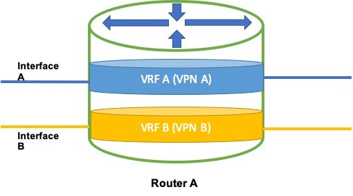
Image 1 – VRF Anatomy of a Router
The concept of Virtual Routers is used because when the data, part of a VPN, needs to be carried through a device, the device should know from where the data packet came and where it should be sent. VRF divides the Global Routing Table of a router into multiple and specific virtual routing tables, where each routing table acts independently as if it was working for a specific VPN.
What this means is that if a packet arriving on a router is for a specific VPN, the packet will be checked against the concerned virtual routing table and then would be forwarded to the next hop based on the table entries.
Enabling Virtual Routing and Forwarding on a Router
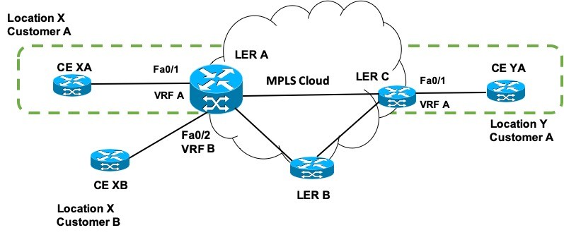
Image 2 – Virtual Routing and Forwarding Example with an MPLS cloud
Example Setup
Let us have a look into how VRF works on a router. Consider Image 2. Here we have considered an MPLS network with 3 label edge routers LER A, LER B, and LER C. LER A (which is enlarged) is connected to the Customer A and Customer B customer edge (CE) networks (at location X) via CE XA and CE XB. These Customer Edge Routers are connected with LER A on its Interfaces Fa0/1 and Fa0/2 respectively.
- Virtual Routing and Forwarding (VRF) can be seen to be configured on the LER A interfaces.
- For Customer A, we have VRF as VRF A which is configured on Fa0/1.
- For Customer B, we have VRF as VRF B which is configured on Fa0/2.
- Another label edge router LER C connects the edge network of Customer A at location Y via CE YA. The interface Fa0/1 is also configured with VRF A.
Expectation
Now, we want the data packets to flow from LER A to LER C i.e. from customer location X to customer location Y in a private mode. Location X could be Dallas, Texas, and location Y could be Los Angeles, California where Customer A has its offices.
Suppose, Customer A also has departments AB and CD at both the locations.
The requirement is that the network configuration should be such that the employees of department AB sitting at location X should be able to communicate only with the employees of department AB sitting at location Y.
Thus, what customer A wants is a VPN across his offices and also within the departments. The communication between the departments at different locations should be one on one and private.
What should be enabled
Before we proceed any further, we need to realize that VRF cannot work independently. Some functionalities should be pre-enabled for VRF to work.
- Cisco Express Forwarding (CEF) should be enabled (or, any other Fast Switching mechanism that is currently used as per the device vendor).
- Needless to say, MPLS should be enabled.
- Label distribution protocol (LDP) should be enabled.
- An Internal Gateway Protocol (OSPF, IS-IS, etc.) should be active in the MPLS network.
- Routing protocol to advertise routes from the customer network to the MPLS network should be enabled (BGP, EIGRP, etc.).
- Internal BGP or iBGP should also be enabled.
When all these conditions are met, we can configure and enable VRF on edge routers. VRF is configured on a per-interface basis, and so we need to ensure that the concerned interface is active (Administratively up) and accepting data packets.
The green dotted line in Image 2 shows that Fa0/1 on LER A and LER C are part of the same VLAN. They look to be directly connected (though they are not) just as in VLAN.
Here’s how VRF is configured:
LER A# configure terminal
LER A (config)# ip routing
LER A (config)# ip vrf VRF A
LER A (config-vrf)# rd 1:1
LER A (config-vrf)# route-target export 1:1
LER A (config-vrf)# route-target import 1:1
LER A (config-vrf)# exit
How Virtual Routing and Forwarding works?
Let us consider the network in Image 3.
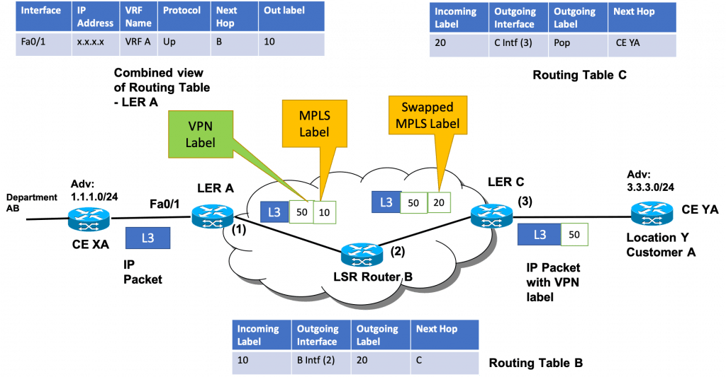
Image 3 – Virtual Routing and Forwarding working
Once all the configuration is in place, the VRF will come into action. A VRF table will be created for every Customer, unlike the global routing table which contains all the unique routing entries for a device. Let us see what all happens if department AB of Customer A at location X needs to communicate with the same department at location Y.
Setup and Expectations
- LER A is shown with a combined view of the Routing table, Forwarding table, and VRF table.
- Suppose Customer A at location X is advertising routes – 1.1.1.0/24 for Department AB.
- Suppose Customer A at location Y is advertising routes – 3.3.3.0/24 for Department AB.
- These advertised routes are saved by all the Label Edge Routers based on the routing protocol which is used between the Customer and the MPLS networks.
- Let us suppose that a person in department AB at location X needs to download a file from the server in department AB and at location Y.
- The routing and forwarding tables on the Edge routers and label switch routers would also be in place based on internal gateway protocol and CEF.
Working
- When an IP packet (for file download request) will arrive on LER A via CE XA, LER A will reference the VRF table and find out that VRF A is configured on the interface Fa0/1 and is an Active VRF.
- As soon as the IP packet is realized to be related to VRF A, an identification VPN label for VRF A is added to the IP packet (Let us say that routes 1.1.1.0/24 are assigned label 50.)
- Now, as the IP packet needs to travel through the MPLS network, a transport label (label 10) shall also be attached, but over the top of the VPN label.
- The VPN label 50 will be available with every label edge router which will help the LERs to identify a specific VRF or VPN. This sharing of information of label value is made possible using iBGP.
- Using the transport label, the packet shall move across the MPLS label switch routers and will finally reach LER C. This mechanism is already discussed in our Multiprotocol Label Switching post.
- Considering a non-PHP scenario (Penultimate Pop Hopping), the transport label shall be stripped off at LER C like in any MPLS solution.
- Once the transport label is removed, the router will then be left with only the VPN label. LER C will then verify the VPN label with its VRF and related tables.
- Once an entry is found, the VPN label will be stripped off and the native IP packet would then be forwarded to the required destination.
All the VPN-related mechanism is happening at the IP level. There is no use of L2 information as such in deciphering the VRF logic.
Though, L3VPN is a broader term that encapsulates VRF. While L3VPN is a service, VRF is a technology that is used by L3VPN.
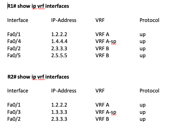
Cisco VRF Command
The following command can be used to display the VRF configuration on a Cisco device. Here we have VRF A and VRF B for Customers A and B respectively. In most of the cases, the VRF name will be a proper and identifiable name.
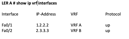
Note: The output may be different from the actual output
show ip vrf brief command can also be used here.
Virtual Routing and Forwarding based Topology (Hub-Hub and Hub-Spoke)
There are times when a customer or network engineer would want to see the topological view of their VRF network. This would enable them to realize if their VRF configuration is correct or not, and all their VRF-related network devices are enabled.
There can be many topologies that can be enabled but the two famous ones are Hub-Hub (Mesh) and Hub-Spoke. Such type of information could be provided or seen on an NMS (Network Management System) or EMS (Element Management System).
To identify if a VRF or PE interface is part of Hub or Spoke, a specific configuration could be required from where such information would be fetched. One example is the VRF Name column in the VRF table. A VRF name could be defined in such a way that it could be easily identified as part of Hub or Spoke.
Example: Let us assume the following configuration for 2 LER’s. The spoke is denoted by the suffix “-sp”.
In the above configuration, VRF A has two spoke locations and two Hub locations with R1 and R2. The HUB and HUB of R1 and R2 are shown to be connected by the dotted line. Hub-Spoke locations are connected by orange and blue lines with the Hub.
Hub-Spoke Topology
Also, VFB A has locations in Hub-Spoke topology. The Hub-Hub locations are interconnected, while others are attached as Spokes to the Hubs. Following is the sample Hub-Spoke topology.
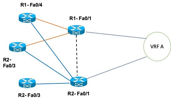
Image 4 – Hub-Spoke VRF Topology
Hub-Hub Topology
VRF B has all Hub locations and thus they would be interconnected. This type of topology is also called Mesh topology. Following is the sample Hub-Hub topology or Mesh Topology.
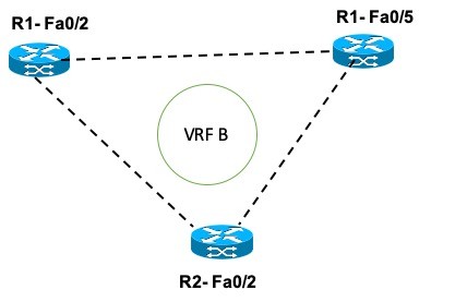
Image 5 – Hub-Hub VRF Topology
The core idea is that if the interfaces are connected as a Hub for a VRF, then they are directly connected and can exchange information.
If the interfaces are part of Hub-Spoke, each Spoke is attached to the Hub. So, any communication from a Spoke location will be done via the HUB location instead of direct communication.
Conclusion
That’s it. This is all that happens in the VRF. Easy, right? Not really. There are a number of different processes and protocols that work seamlessly to achieve the desired results that we have not talked about yet.
The knowledge here is only half-baked and is targeted to give a high-level overview of what VRF is all about. Check out our next post on how VRF works which will focus on the actual detailed functionality of VRF.
Virtual Routing and Forwarding: FAQs
Virtual Routing and Forwarding or VRF can be treated as a technology equivalent to VLAN but works at Layer 3. VRF is a feature where an edge router, part of the MPLS network, supposedly turns into multiple virtual routers, and data across different customer locations is carried separately just as it would be in the case of a VPN.
When all these conditions are met, we can configure and enable VRF on edge routers. VRF is configured on a per-interface basis, and so we need to ensure that the concerned interface is active (Administratively up) and accepting data packets.
A VRF interface is an interface on provider edge router on which VRF is configured. This interface faces the customer edge device.
Good Reads & References
CURATED & WRITTEN BY
AYUSH PANDYA
(AUTHOR – THE UNPRECEDENTED CULT)