Table of Contents
A Quick Recap
In the last article, we discussed Virtual Routing and Forwarding, or VRF, at a high level. In this article, we will detail how the VRF actually works.
Before moving ahead, let us keep the following pointers handy from our last discussion:
- Virtual Routing and Forwarding (VRF) is not a simple term but a technology used in L3VPN.
- Virtual Routing and Forwarding, conceptually, divides the global routing table of a device into multiple VRF based virtual routing tables.
- Using the concept of virtual routing tables, different customers with the same advertising routes can co-exist on a device.
- Virtual Routing and Forwarding works similar to VLAN but at Layer 3.
- Basically, VRF is configured on the L3 device interfaces.
- MPLS, CEF, and Internal gateway protocols should be enabled because they define the core functionality of VRF.
- iBGP or MP-BGP should be in place.
- VRF makes use of a VPN label. It is separate from the Transport label which is an entity of MPLS.
- VRF configuration is usually done at the edge devices of the MPLS network because that’s where the VRF tagging and identification is done.
How VRF works: Entities in Virtual Routing and Forwarding
There are few entities in Virtual Routing and Forwarding that form the base of how the VRF actually works.
Route Distinguisher (RD)
Let us start with an understanding of all the features and processes that are part of the VRF solution. The first thing that is relevant and important is an entity called Route Distinguisher or RD.
As already stated, using VRF, the same advertised prefixes from different customers can co-exist on a device. For example, if there are two Customers (Customer A & Customer B) and both are advertising 192.168.1.0/24 routes, tagging each of them to a unique VRF can keep them isolated and thus make them co-exist on a router.
This is where Route Distinguisher comes into the picture.
Using a unique Route Distinguisher for a VRF, the advertised routes can be segregated and identified in a VRF-enabled MPLS network. Without RD, we will not be able to determine if a packet is destined for Customer A or Customer B.
In a nutshell, RD acts like a header value that gets prepended to the advertised routes and is saved by all the Provider Edge (PE) routers using MP-BGP which we will discuss later.
Route Distinguisher is of 64 bits. The Route Distinguisher comprises of three fields i.e. Type field (2 bytes), an Administrator field, and Assigned Number field. The value of the type field actually derives the other two fields.
Route Distinguisher Format
There are currently three defined formats of the Route Distinguisher’s type field. The following pointers show the “type” value and the corresponding possible values of the other two fields.
- Type 0 – 2 bytes of ASN value and 4 bytes of the normal integer value. Example 0:64000:100.
- Type 1 – 4 bytes of IP address and 2 bytes of the normal integer value. Example 1:192.168.1.0:100
- Type 2 – 4 bytes of ASN value and 2 bytes of the normal integer value. Example 2:64000:100
Public ASN should be used where ASN used in the formats.
The format chosen could be any one of the above, but, it should be unique for each VRF. For protocols, RD is just a number but identifies the routes and VRF.
Example of Route Distinguisher Configuration
R1(config)#ip vrf VRF A
R1(config-vrf)#rd 64000:10
Based on what values are configured, the type of RD can be derived. Use the following command to verify the Route Distinguisher configuration.
R1#sh ip vrf
Name Default RD Interfaces
VRF A 64000:10
Once the configuration is complete, the routes are advertised with RD prepended. For example, the advertised route information would be like 64000:10:192.168.1:0/24.
Route Target (RT)
The other important entity in VRF is Route Target or RT. Where RD is required to uniquely identify the routes of various customers or VRFs, Route Target helps in identifying which routes should be accepted and exported for a particular VRF. Using Route Target, the device can import different routes that are advertised by various Provider Edge Routers. So, even the overlapping routes can be accepted by a device based on what Route Target configuration is in place, but of course, they would be unique as per the Route Distinguisher and unique Route Target values.
Route Target and Route Distinguisher may seem to be the same, but they have different functions. While RD specifically makes the routes unique for different VRFs, RT defines which all routes from the VRFs should be advertised and consumed.
Just like RD, RT is also an 8-byte entity. There is no hard and fast rule of what should be the values of Route Target.
Following is an example of Route Distinguisher (RD) Configuration.
R1(config)#ip vrf VRF A
R1(config-vrf)#rd 64000:10
R1(config-vrf)#route-target export 2:2
R1(config-vrf)#route-target import 1:1
Route Target Example
Let us take an example and discuss how Route Target actually works. Consider Image 1 below. Here we have an MPLS network with 3 LERs (LER A, LER B, and LER C), however, at different locations. LER A has been configured with VRF A. Label Edge Router B has been configured with VRF B. LER also has VRF A configured.
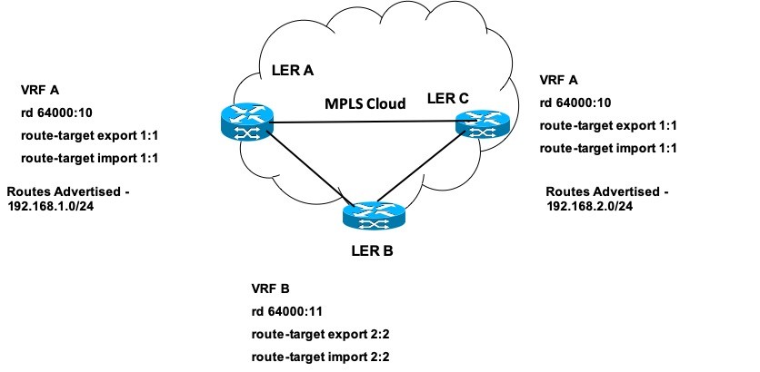
Image 1 – VRF, Route Distinguisher, Route Target Example
The values for RD are depicted in the Image. For VRF A, RD is 64000:10 and for VRF B, RD is 64000:11. Using these RD values even the overlapping routes will be unique.
Now, let us see the Route Target (RT) values.
- For LER A and VRF A we have Route Target Export values as 1:1 and that of Import as 1:1.
- For LER B and VRF B we have Route Target Export values as 2:2 and that of Import as 2:2.
- For LER C and VRF A we have Route Target Export values as 1:1 and that of Import as 1:1.
The values for Export and Import Route Target can be different.
Working
The LER A is configured with VRF A and can export routes with Route Target value as 1:1 while it can also accept routes with RT value as 1:1. The VRF B which is configured on LER B can accept routes with RT value as 2:2 and can export routes with RT value as 2:2.
LER C, which is configured with VRF A can import and export routes with values the same as in LER A i.e. 1:1 and 2:2 respectively.
The sample advertised routes are also depicted in the Image. LER A learns the route 192.168.1.0/24 while LER C learns the route 192.168.2.0/24. Both the routes are advertised with Route Target values as 1:1. Now, as both the routes are marked with RT as 1:1, LER C will be able to accept Route 192.168.1.0/24 from LER A, and LER A will be able to accept Route 192.168.2.0/24 from LER C. Thus, LER A and LER C have information of both the routes of VRF A.
VPNv4 Routes
VPNv4 routes are just like IPv4 routes but are considered to be the part of the VRF feature together with MP-BGP (which is extended BGP communities). The VPNv4 route is the combination of Route Distinguisher and IP Address of the routes. Thus, VPNv4 is a 12-byte entity. For example, 64000:10:192.168.1.0/24 that we discussed in the earlier section is a VPNv4 route.
A VPNv4 route is unique across the various VRF routes.
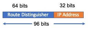
Image 2 – VPNv4 route format
MP-BGP
Multiprotocol BGP or MP-BGP is an extension of the Border Gateway Protocol. The name “Multiprotocol” is derived because this extended BGP can distribute different types of IP Addresses as compared to standard BGP that deals with only IPv4 addresses.
MP-BGP supports both IPv4 and IPv6 addresses and variants like unicast and multicast address types.
MP-BGP in L3VPN takes charge of the control-plane, while on the data-plane, the packets move as a normal packet does in an MPLS network.
Once MP-BGP is enabled on the MPLS cloud, the routes received by the edge router are converted from IPv4 to VPNv4 routes. Using the Route Distinguisher makes the route unique even if they are overlapping between different customer VRFs.
Using MP-BGP, the information of routes advertised reaches every label edge router of the MPLS cloud. A VPN label is assigned to the specific route(s) in a VRF and the information is carried to all the LERs.
There is however a challenge with this advertisement to all the LERs. If each LER starts advertising the VPNv4 routes to other LERs, then, as more and more routers will get added to the MPLS cloud mesh, the process of advertisement and capturing will load the routers. Thus, Route Reflectors are generally used for the advertisement of the VPNv4 routes.
Route Reflector
A Route Reflector (RR) has the responsibility to push any BGP update received from an LER to all the other LERs in the network. This process reduces the load on each LER because they now have to form a single BGP session with RR for advertising the route updates. The mechanism greatly reduces the load on the individual LERs. Each LER pairs with the Route Reflector and sends the route updates to the RR only. RR then forwards the updates to all the other LERs. There may be more than one RR used if the topology is complex. A backup Route Reflector is also added which becomes active when the Primary Route Reflector fails.
Let us see how MP-BGP and RR can be configured.
R1> enable
R1> configure terminal
R1(config)> router bgp 200
R1(config-router)> neighbor 10.1.0.1 remote-as 200
R1(config-router)> neighbor 10.1.0.1 activate
R1(config-router)> address-family vpnv4
R1(config-router-af)> neighbor 10.1.0.1 send-community extended
R1(config-router-af)> neighbor 10.1.0.1 activate
R1(config-router-af)> end
Commands Courtesy: Cisco.com
What is VPN Label and how it works in VRF?
As discussed above, the VPN label is used to identify customer route(s) in a particular VRF. This is a data-plane feature and is used to send an IP packet to the correct customer location. The addition of a VPN label with a transport (MPLS) label creates a label stack in the IP packet. While the Transport label is used in the MPLS network for forwarding, the VPN label is to identify a specific customer destination because there is no other entity that can do the job.
VPN label is crucial in defining how the VRF works. The label is carried via MP-BGP to all the LERs. A VPN label is 32 bits long.
There are two methods of VPN or L3VPN label allocation.
- Per Prefix – Where each route is assigned a unique label. This can create a challenge because a large number of routes and thus labels can consume the memory.
- Per VRF – A single VPN label is allocated for all the local routes in a VRF.
How VRF works?
Now, that we have discussed all the entities of VRF, let us join the dots of how the VRF actually works.
What do you need to do?
The VRF works by combining the entities: Route Distinguisher, Route Target, and MP-BGP. VPNv4 routes and VPN labels are thus shared with each Label Edge Router that forms the base of VRF working. The following are the detailed steps of how VRF works as part of the MPLS network.
- Enable CEF (Mostly enabled by default in current Cisco devices).
- Enable MPLS globally and at the interface level.
- Enable the Label Distribution Protocol (LDP).
- Enable an IGP protocol (OSPF, IS-IS, etc.).
- Enable routing protocol between MPLS Edge Routers and Customer Edge Routers (EIGRP, BGP, etc.)
- Once all the protocols are in place, configure the VRFs on the interfaces of edge routers.
- Configure Route Distinguisher for each VRF.
- Configure Route Target for each VRF for import and export.
- Enable MP-BGP for VPNv4 routes.
Consider Image 3 below for reference.
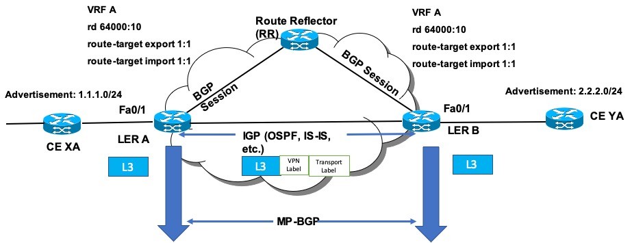
Image 3 – Virtual Routing and Forwarding Working
Working
Route Target & Route Distinguisher
- Suppose Customer A at location X is advertising routes – 1.1.1.0/24.
- Suppose Customer A at location Y is advertising routes – 2.2.2.0/24.
- The VRF, RD, and RT configuration for LER A and LER B is also shown in the image. The configuration of these entities defines how the VRF works.
- Both the Routers have the same Route Target values.
- Based on the Route Target values, both LER will import each other’s routes as per the process that we discussed in the last section.
- When a routing protocol is configured between Customer Edge and Provider Edge routers, the routes will be advertised by the Customer Edge Routers (CE XA and CE XB) and will be captured by the Provider Edge Routers (LER A and LER B).
MP-BGP
- Due to MP-BGP, the IP routes captured are converted into VPNv4 routes using the Route Distinguisher that was configured for the VRF A. For e.g. the VPNv4 route would look like – 64000:10:1.1.1.0/24
- The VPNv4 routes are also tagged with Route Target values.
- The MP-BGP creates VPN labels for the routes.
- A route advertisement thus is a mix of VPNv4 route, Next Hop LER loopback address, VPN label, and Route Target attached with the VRF.
- The edge routers (LER A and LER B) share the routing information and the VPN labels with Route Reflector RR.
- RR then forwards the updates to the LERs. The updates from LER A will be sent to LER B and vice versa via RR.
- MP-BGP works at the control-plane. All the VPNv4 routes and VPN labels are available with every Provider edge router through MP-BGP. The routes captured are available via Route Target working.
E2E Working
- Suppose, an IP packet arrives at LER A on Fa0/1 for destination 2.2.2.1 which is reachable via LER B.
- LER A and LER B would have already shared the information about the route destinations reachable through MP-BGP.
- The LER A will look up its VRF table and will conclude that the packet is meant for VRF A. The required VPN label would be attached to the IP packet first.
- As the packet has to flow through the MPLS network, a transport label would also be tagged above the VPN label.
- Once inside the MPLS network, the packet will flow as per the MPLS process by swapping labels.
- Using the MPLS Forwarding table, the packet will arrive at LER B. The transport label may or may not be stripped off at LER B (based on Penultimate Hop Popping).
- Once the transport label is stripped off, the LER B will find the VPN label and will check its entries.
- Based on the label information gathered from MP-BGP, the device will conclude that the VPN label is for VRF A. The VPN label will then be stripped off from the IP packet and would be sent towards the concerned Customer Edge router.
How VRF works: FAQs
Using a unique Route Distinguisher for a VRF, the advertised routes can be segregated and identified in a VRF-enabled MPLS network. Without RD, it would be difficult to determine to which customer/VRF the packet actually belongs.
Where Route Distinguisher is required to uniquely identify the routes of various customers or VRFs, Route Target (RT) helps in identifying which routes should be accepted and exported for a particular VRF.
VPNv4 routes are just like IPv4 routes but are considered to be part of the VRF feature together with MP-BGP (which is extended BGP communities). The VPNv4 route is the combination of Route Distinguisher and the IP Address of the routes and is a 12-byte entity.
Multiprotocol BGP or MP-BGP is an extension of the Border Gateway Protocol. The name Multiprotocol is derived because this extended BGP can distribute different types of IP Addresses as compared to standard BGP that deals with only IPv4 addresses.
The VRF works by combining the entities: Route Distinguisher, Route Target, and MP-BGP. VPNv4 routes and VPN labels are shared with each Label Edge Router that forms the base of VRF working.
Conclusion
That is a wrap-up of our second part of Virtual Routing and Forwarding. I hope the combination of both parts would have given you a good idea of how VRF works. The content is kept simple. I hope you guys enjoyed the post and gained some insights into the topic. Let me know your thoughts in the comments section below.
Good Reads and References
CURATED & WRITTEN BY
AYUSH PANDYA
(AUTHOR – THE UNPRECEDENTED CULT)