Table of Contents
Introduction
Within an Autonomous System (AS), the Interior Gateway Protocols (IGPs) are in action. These protocols take care of the routing and forwarding of the IP packets within the AS. Routing Information Protocol (RIP), Open Shortest Path First (OSPF), Intermediate System to Intermediate System (IS-IS), Enhanced Interior Gateway Routing Protocol (EIGRP), are all examples of Interior Gateway Protocols.
BGP is majorly deployed as an Exterior Gateway Protocol.
For more details on BGP, check out our article: Border Gateway Protocol – An Introduction.
In this article, we will talk about the basic concepts of OSPF and some of its properties. We will briefly discuss the working of the protocol and also look at some basic terms around it.
Note: Check the Appendix section for items tagged with *
Before anything else, let us discuss the two types of IGPs used in the telecom industry i.e. distance-vector routing protocols and link-state routing protocols.
Distance-vector routing protocols
These protocols calculate the best route for the data packets using distance. Distance is the number of routers a packet has to pass through to reach a destination. One router counts as one hop. EIGRP (advanced distance-vector routing protocol) and RIP are examples of Distance-vector routing protocols. In the distance-vector protocol, the neighbors exchange routing tables and hop counts.
The Bellman-Ford algorithm is behind the calculation of the best path in distance-vector protocols
Link-state routing protocols
In the link-state routing protocol, each router has complete information about the network topology. The best route is calculated by identifying the best next-hop and combining the data to get the best route to a destination. OSPF and IS-IS are examples of link-state routing protocols.
The routers exchange Link-state Advertisements or LSAs to build the network topology.
What is Open Shortest Path First (OSPF)?
Open Shortest Path First or OSPF, is one of the most popular Interior Gateway Protocols for the IP network.
It uses Link State Advertisements (LSAs*) to build a Link State Database (LSDB). This database has all the possible routes and links to build the best paths.
Configured on interfaces, OSPF uses Dijkstra’s or Shortest Path First (SPF) algorithm to calculate the best route to a destination.
Cost in OSPF
Open Shortest Path First protocol uses bandwidth as one of the metrics to calculate the shortest path to a destination. It is known as the cost of the route.
The OSPF cost is inversely proportional to the bandwidth of the interface. This means that the higher the interface bandwidth, the lesser the cost. The following formula calculates the OSPF interface cost:
Cost of an interface= reference bandwidth/interface bandwidth
The total cost of a route is the sum of all the costs of the interfaces. The reference bandwidth by default is 100,000,000 bps. Update the reference bandwidth on all the OSPF routers if changed.
Suppose we have a 10 Mbps Ethernet link. The interface cost as per the formula will be 100,000,000/10,000,000 = 10.
Thus, it costs 10 to cross a 10 Mbps link. Similarly, for a 1 Mbps link, it costs 100.
The interface bandwidth is in bps to determine the cost of the interface. Also, the minimum cost is 1 and cannot go below it.
A route with the lowest cost is taken as the best route in a network.
Here is the cost of specific interfaces:
| Link | Bandwidth | OSPF Cost |
| Serial | 56000 | 10^8/5,600 =~ 1785 |
| T1 | 1,544,000 | 10^8/1,544,000 =~ 65 |
| Fast Ethernet | 100,000,000 | 10^8/100,000/000 = 1 |
| Gigabit Ethernet | 1,000,000,000 | 1 (Cost can’t be less than 1) |
Basic Properties of OSPF
Let us quickly go through some of the properties of OSPF:
- Open Shortest Path First (OSPF) is enabled on router interface(s).
- Router ID(RID*), a 32-bit dotted number (not necessarily IP), identifies a router in the protocol topology.
- It is a classless routing protocol.
- The Administrative Distance (AD) of OSPF for Cisco is 110.
- The Open Shortest Path First (OSPF) protocol updates are exchanged on a per router basis. This means that when an update is noted at the router, it is sent to the neighbor router which further updates its neighbors.
- OSPF has a good convergence which means that it takes a small amount of time for all the OSPF routers to get updated with the OSPF routing information.
- The protocol has no limitations. Unlike some other protocols, OSPF can work on as many routers as possible.
- All the OSPF routers in an area have an identical Link State Database (LSDB).
- There is no restriction on vendor devices. The protocol can work on any vendor device.
- OSPF also provides neighbor authentication. The authentication can be via simple password, or SHA, or MD5 encryption.
- The protocol supports the concept of multi areas where a bigger area can be fragmented into multiple small areas. This configuration reduces the load on the OSPF routers.
Tables in OSPF
OSPF has three tables that are created stepwise while creating the neighborship and adjacency between the two routers.
The following are the tables:
- Adjacency/Neighbor table – This table stores the neighbor information.
- Link state or Topology table – This table stores all the LSA information gathered from other OSPF routers. It contains all the possible OSPF paths.
- Routing table – Once the above two tables are in place, the SPF algorithm is run and the best routes are dumped in this table.
The following are the Cisco commands associated with each of the above tables:
| Table | Command(s) |
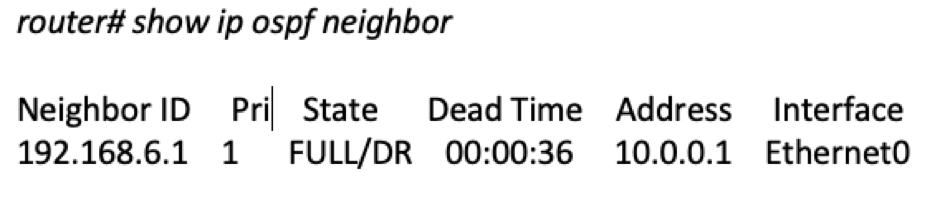
| Adjacency/Neighbor | show ip ospf neighbor |
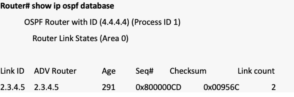
| Topology/Link state | show ip ospf database |
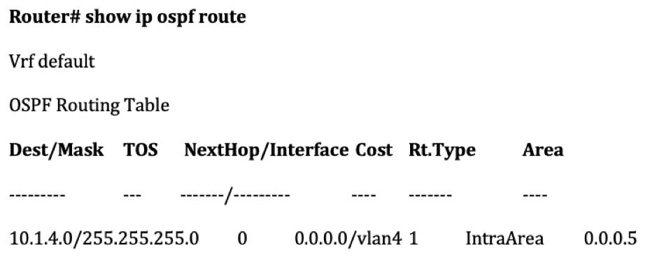
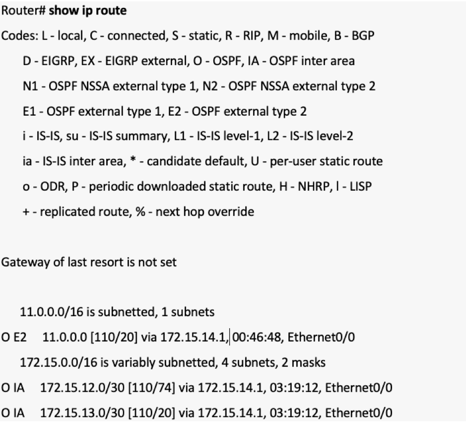
| Routing | show ip ospf route, show ip route |
For commands output, check the section “OSPF Commands“.
Concept of Areas in OSPF
Areas hold significant importance from the OSPF perspective. An Area is a marker or a set of network nodes within an AS where all the routers are part of the same OSPF process and have identical Link State Database (LSDB). An area can have all the OSPF routers in the topology or there can be multiple areas that consist of a set of OSPF routers.
An Area is denoted by a number and can have any value. When there are multiple areas in the topology, Area 0 is a must, and all the areas should be connected to Area 0.
Area 0 is also called a Backbone/Transit area
ABR and ASBR in OSPF
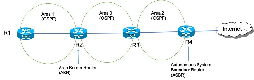
There are two types of routers from the OSPF point of view: Area Border Router (ABR) and Autonomous System Boundary Router (ASBR).
As per RFC 3509, an Area Border Router (ABR) is a router that connects two or more areas under the OSPF influence. An ABR should have a minimum of one interface in an area and one of the areas should be Area 0.
An ABR connects an area with the backbone area/Area 0.
It is through ABR only that the routes or LSDB in an area can be injected into the other area(s). Thus, ABR acts as a bridge between the areas.
An Autonomous System Boundary Router (ASBR) is a router that is found in between two Autonomous Systems (ASes), where one AS is configured with OSPF, while the other AS is generally controlled by a non-OSPF protocol. ASBR acts as a carrier to inject external routes into the OSPF domain.
The OSPF cost is calculated area-wise and given to ABRs for further processing. So, if we have a route in Area 2 (consider topology in Image 2) and we have to calculate cost from Area 1, the total cost would be Cost in Area 2 + Cost in Area 0 which is given to Area 1. Only the best route cost is provided by ABR.
Types of packets in OSPF
There are 5 types of OSPF packets:
- Hello
- Database Description (DD)
- Link-state Request (LSR)
- Link-state Update (LSU)
- Link-state Acknowledgment (LSAck)
Hello Packet
Using hello packets, the neighbor or adjacency table is built. Hello packets help in neighbor discovery which is the first step to forming a full OSPF adjacency.
Hello packets are also used as KEEPALIVE messages and are sent every 10 seconds to detect the status of their neighbor. The most important part of the Hello packet is the exchange of certain initial parameters. These parameters should be matched before an OSPF neighborship is formed.
The following are some of the parameters in Hello packets that are exchanged between the two adjacent OSPF routers:
- Timer value (Default – 10 seconds). The packets are sent every 10 seconds to the neighbor.
- Dead interval (Default – 40 seconds). If the hello response is not received from the neighbor within 40 seconds, the source router treats the neighbor router as dead and the OSPF connection is terminated.
- If there is a specific authentication mechanism applied between the two OSPF routers, their passwords should match.
- The subnet mask of the routers should match, or precisely, the interfaces under the OSPF influence should be part of the same subnet.
- The Area of both the routers should be the same.
- Their Router ID (RID*) should be unique.
From the networking point of view, the source router sends the hello packets on multicast address 224.0.0.5. This IP helps routers understand that they can accept messages destined to 224.0.0.5 as part of the OSPF process.
Once the hello parameters are matched, the neighbor router sends back its hello message on 224.0.0.5 with its RID and RID of the neighbor router. If everything goes well, a neighborship is formed between the routers and further actions can be performed.
Database Description Packet (DD)
The Data Description packet or DD packet comes into action when the neighborship is formed between the two routers.
The immediate packet that is sent after the hello packet is the DD packet. A brief summary of the LSAs that are present in the source router is exchanged with the neighbor router. From the neighbor’s perspective, it checks the LSA summary against the LSA data it has and sends back a request to the source router to get all the details of the missing LSAs.
Link-state Request Packet (LSR)
Once the neighbor router has identified the missing LSAs, it sends back a Link State Request (LSR) packet to the source router asking for the full LSA details.
Link-state Update Packet (LSU)
The link-state update packet is the response to the LSR packet. LSU is a big packet as it contains the full details of the LSAs. Once the LSU is received by the neighbor router, it updates its Link-state Database (LSDB).
Link-state Acknowledgement (LSAck)
The Link-state Acknowledgement (LSAck) is an acknowledgment to the source router sent by the neighbor router denoting that it has received the LSA details and has updated its database.
Following the exchange of LSDB, the SPF algorithm is run and the best routes are calculated.
Neighbor States
There are namely seven neighbor/router states defined in the OSPF:
- Down
- Init
- 2-way
- Exstart
- Exchange
- Loading
- Full
The following is a brief description for each:
Down
Down is the initial state when no hello packets are exchanged between the adjacent routers. In this state, the Router ID is selected for each router for future information exchange.
Init
The state changes from Down to Init once the hello packets exchange process starts. This happens immediately after OSPF is enabled.
It is here that the hello packets are sent and received by the routers and the parameters are verified for compatibility.
2-way
The 2-way state is achieved after the hello packets between the routers have been exchanged and the parameters have been accepted. The selection of a Designated Router (DR) and a Backup Designated Router (BDR) happens at this step.
Exstart
Once the DR* and BDR* are selected, the state changes from 2-way to Exstart. In this state, a master-slave selection happens between the two OSPF routers. Generally, the router with the highest RID takes the responsibility of the master and starts the LSA exchange process.
The OSPF packet sequencing is taken care of by the master router. Sequencing helps in maintaining the order of the OSPF packets and discarding any redundant packets.
Exchange
After the master-slave selection, the state changes to Exchange. Here, the database description packets are exchanged between the two routers. In this state, LSA header information is exchanged. Once the slave router gets the LSA information, it matches it against its LSDB. Once it identifies a new LSA, it requests the Link-state information from the master router.
Loading
When a Link-state request (LSR) is sent to the master router, the state changes from Exchange to Loading.
Once the LSR is received by the master router, it sends back the full information (part of the LSU packet) of the missing LSAs to the slave router. The slave router then accepts the LSAs and dumps them in its LSDB. Following this, a Label-state Acknowledgement (LSAck) is sent back by the slave to the master router.
Full
When the full LSA information has been exchanged and both the routers have identical LSDB, the state is changed from Loading to Full. After Full state, the two routers are said to be fully OSPF adjacent.
The SPF algorithm is now run and the best routes are selected and dumped in the Routing table.
To check the state of an OSPF router at any given point in time, we can use the Cisco command “show ip ospf neighbor”
OSPF Commands
1. show ip ospf neighbor
2. show ip ospf database -This command also has multiple options
3. show ip ospf route
4. show ip route (Check the prefix O for OSPF routes)
5. OSPF Configuration
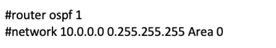
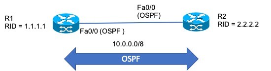
The “router ospf 1” command initializes the OSPF process with process id* as 1. The network command enables OSPF on network 10.0.0.0 which will be a part of Area 0.
Appendix
What is a process id in OSPF?
The process id in OSPF is a Cisco convention. A process id is local to a router and uniquely identifies an OSPF process.
By using different process ids, separate OSPF processes can be enabled on a single device. These OSPF processes don’t interfere with each other. The process id value can be between 1 – 2^32.
In EIGRP, AS Number is used rather than process id
What is a Router ID (RID)?
Router ID or RID is what uniquely identifies an OSPF router in a topology. RID is in dotted 32-bit number format and is not necessarily an IP address. A Router ID is an identifier that uniquely identifies a router in an OSPF domain.
How Router ID is selected?
There are multiple ways by which the Router ID is selected.
- Manually – The administrator can manually assign a router-id to a router. As stated earlier, the router id is a 32-bit dotted number and is not necessarily an IP address. Manually configuring the Router ID is considered to be the best way to assign a router id.
- Using Loopback – If a router has a loopback interface enabled and is not manually configured for the Router ID, the loopback is treated as the Router ID. If there are multiple loopbacks enabled on a router, the highest loopback IP is selected as the Router ID.
- Using Interface IP – If the router is not manually configured and has no loopback interface enabled, the physical interface with the highest IP address is considered to be the Router ID.
It should be noted that in case the Router ID is selected by the automatic process, the interface whose IP is treated as a Router ID should be UP. Also, if the Router ID has been manually configured, the automatic selection process will not happen.
Configuring the Router ID manually helps in retaining the Router ID even when the router is reset.
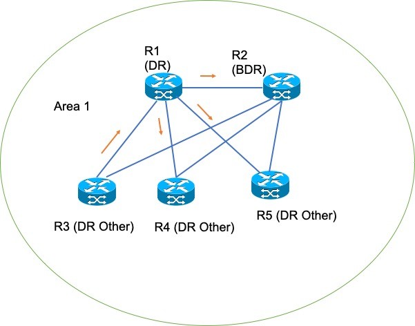
What are DR and BDR routers in OSPF and why are they required in Broadcast Multiaccess Network?
Designated Router (DR) and Backup Designated Router (BDR) selection is an important process in OSPF.
The selection happens during the 2-way state (check the states in the previous section) and is specific to Broadcast Multiaccess Network (where multiple nodes share a LAN segment). If the two links are point-to-point (P2P), then the 2-way state is never achieved i.e. the state changes from INIT to Exstart.
P2P links are Serial links while Fast Ethernet or Gigabit Ethernet links are part of the Broadcast Multiaccess Network.
In a multiaccess network, any Link-state information received by a router from the neighbor router is recorded and sent over to other links. This creates a flooding loop. To prevent this flooding and choking in the broadcast multiaccess network, DR (Designated Router) and BDR (Backup Designated Router) are selected with which the other routers in the area form an adjacency with them rather than with each other. It is the responsibility of the DR (or BDR, if DR fails) to send Link State Updates to other routers. DR and BDR are also OSPF adjacent routers and have identical LSDB.
If in a broadcast multiaccess network DR is not selected, the adjacency will never be formed.
How are DR and BDR selected?
In a multiaccess broadcast network, the selection of DR and BDR is important. A router can be assigned a priority between 1 – 255. The router with the highest priority becomes DR and the second-highest priority router becomes the BDR.
The routers with priority 0 will never take part in the DR/BDR process.
If the priority is identical, then Router ID is checked. The router with the highest Router ID becomes the DR.
When the first router is configured for OSPF and reaches the 2-way state, it waits for 60 seconds to capture any DR-based message. If no message is received, the router considers itself the DR.
Once the DR and BDR are selected, you will have to reset the OSPF configuration to recalculate DR and BDR.
What is LSA in OSPF?
Link-state advertisement (LSA) is the basic unit of communication between the two OSPF routers. Using LSA, all the OSPF-based information, paths, routes, etc. are exchanged between the routers.
There are 11 types of LSAs. LSAs are like informational pieces that are exchanged between two OSPF routers.
The LSA types and their brief descriptions are provided in the table below:
| LSA Type | LSA Name | Description |
| Type 1 | Router LSA | Describes the RID and Link IP Address. Works within area. |
| Type 2 | Network LSA | Describes neighbors connected to the segment. Works within area. |
| Type 3 | Summary LSA | Generated by ABR. Advertises Type 1 and 2 LSAs to other areas. |
| Type 4 | ASBR Summary LSA | Generated by ABR to advertise routes to ASBR. |
| Type 5 | ASBR External LSA | Generated by ASBR to redistribute external routes. |
| Type 6 | Group Membership LSA | Used in MOSPF. Not applicable to Cisco routers. |
| Type 7 | Not So Stubby Area (NSSA) External LSA | Generated by ASBR inside NSSA area. |
| Type 8 | OSPF External Attributes LSA | Not used in Cisco routers. |
| Type 9/10/11 | Opaque LSA | Reserved for future use. Type 10 is used in MPLS-TE. |
How LSA Header looks like?
The LSA header contains information to uniquely identify an LSA type. Here is a sample image of the LSA header.
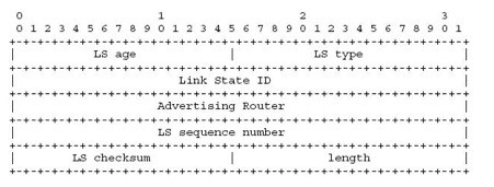
Courtesy – Google
The following are the descriptions of each field as part of the LSA Header:
LS age – Time since LSA was originated.
LS type – Indicates the LSA type as discussed earlier.
Link State ID – Together with LSA type and Advertising Router identifies an LSA in LSDB.
Advertising Router – The Router ID of the LSA originating router.
LS sequence number – For old and duplicate LSA.
LS checksum – Complete checksum of the LSA header.
length – The total length of the LSA including 20 bytes of LSA header.
How to delete an LSA?
To delete an LSA, the refreshed LSA is sent by the source/originating router with a timer of 3600 seconds. Using this timer, the concerned router understands that a particular LSA needs to be removed/flushed from the LSDB.
What is the sequence number in LSA?
As the routers send LSAs at regular intervals, there needs to be a mechanism using which the router knows that the LSAs are processed in sequential order. This is where sequence numbers come into action. When an updated LSA is sent by a source/originating router, it is tagged with a sequence number. When the LSA is received on the destination router, it checks its LSDB and identifies if the LSA contains new information or not. If the sequence number for the LSA is already present, the LSA update will be rejected, otherwise, the sequence number is updated and the information is recorded.
What is the checksum in LSA?
A checksum is sent with every LSA to detect any issues with the LSA. The destination router calculates its checksum and when an LSA is received, it compares the checksum in the LSA with the locally calculated checksum. If both the checksums are the same, then the LSA is considered OK, else the LSA is discarded.
FAQs
OSPF or Open Shortest Path First is an internal gateway protocol (IGP) and is extensively used in networks. You will often see OSPF deployed within an AS of a service provider.
OSPF works on the concept of LSAs or Link State Advertisements. With LSAs in place, the two adjacent OSPF-enabled routers can exchange complete Link State DB. This DB helps in routing and forwarding the data packets in an OSPF-enabled network. An LSA is the basic unit of communication between OSPF routers.
There are 11 types of LSAs, namely LSA Type 1 – LSA Type 11.
OSPF works taking into consideration Link State Advertisements. The LSAs are data units that are exchanged between the OSPF-enabled devices to create LSDB. This LSDB is the source of identifying the best routes in a network.
Good Reads and References
CURATED & WRITTEN BY
AYUSH PANDYA
(AUTHOR – THE UNPRECEDENTED CULT)