Table of Contents
Preface
Ever heard of RIB and FIB in the networking concepts? Yes, these are the routing tables through which the process of packet forwarding and packet switching is achieved across the Service Provider/Customer networks. In this post, we will delve into the Routing Tables i.e. RIB and FIB, which are also considered to be the base routing tables. Also, apart from the base routing tables, we will focus on Cisco Express Forwarding (CEF) also known as Cisco CEF, the currently used, high-speed forwarding mechanism for IP packets across the network(s).
RIB and FIB tables do not require MPLS to be enabled on the networking nodes and are automatically created using the routes advertised by the routing protocols. They can also contain manually configured paths (if required). RIB and FIB act as a foundation for the MPLS based routing tables, a topic we will cover in a separate post.
In the last article where we discussed the MPLS basics, we learned that the data packets flow through the MPLS network using the concept of labels. The use of MPLS labels to forward IP packets is much more efficient than using native IP forwarding. But, whether the native IP forwarding or MPLS based forwarding, both require Routing tables to forward the IP packets to the correct destination. So, the base Routing Tables will be our primary focus in this article.
Introduction
Before talking about specific Routing tables and Cisco Express Forwarding (CEF) which is applicable for Cisco devices only, it is important to understand what a Routing Table is and where is it used.
“Routing table” is probably one of the most popular terms used in the networking domain. It is kind of a database using which the network nodes are able to identify and forward the IP packets to a required destination. The routing table helps a network node (router, switch, etc.) to decide where the IP packet received should be forwarded to (next-hop address, which interface/port the packet should be sent out, etc.) and then forwards the packets based on the information in the Routing table.
The routing table is found in almost every networking node/device that uses TCP/IP (E.g. routers, switches, etc.) Even our laptops/desktops have a routing table. A routing table can be seen as a table that contains all the possible routing information.
Following is an example of Routing table on a Windows desktop.
| Network Destination | Netmask | Gateway | Interface | Metric |
| 10.1.2.0 | 255.255.254.0 | On-link | 10.1.2.122 | 224 |
| 10.128.4.0 | 255.255.255.192 | 10.128.64.10 | 192.168.0.5 | 20 |
| 0.0.0.0 | 0.0.0.0 | 192.168.8.1 | 192.168.8.5 | 100 |
Table 1 – Routing table example Windows
Working with Routing table
The above table provides a snapshot of what a Routing Table looks like. It has 5 values:
- Destination – This is the IP Address of the destination network. The address is related to a network prefix rather than a specific IP address.
- Netmask – Subnet Mask that helps the current host node to calculate the network and host IP values.
- Gateway – The IP address of the networking node where the packet should be sent first to get to the destination node on a different network. “On-link” depicts that the destination is directly reachable from the host.
- Interface – The interface/port on the host through which the packet should be forwarded.
- Metric – A number for each route that helps the host in identifying the best route to reach a certain destination.
The network destination with 0.0.0.0 specifies that any packet that enters the host and has a destination IP that does not match to any entry in the routing table, will be forwarded to default gateway – 192.168.8.1 through the interface with IP – 192.168.8.5.
Note: The values in the above table are random and only used for demonstration purposes. Also, in this post, we will talk about routing tables from the networking nodes perspective (like routers, switches, etc.) and not the Windows or Linux based computers.
Routing and Forwarding
The terms Routing and Forwarding are often used interchangeably, but they are not the same. Routing relates to the processing mechanism using which the paths between source and destination are determined. Which next hop device the packet should be sent to, what should be the exit interface, etc., all the answers are derived as part of Routing. The IP Routing table is created using Routing data.
Forwarding is the mechanism of actually forwarding the packet from one device to another. For example, a packet for a particular destination D received on port PA of router A should be forwarded to router B using the interface PB of router A.
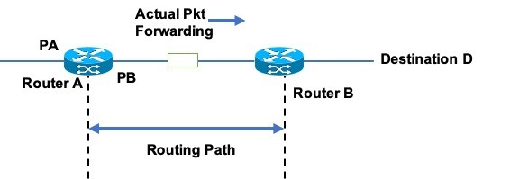
Image 1 – Routing & Forwarding
Control Plane and Data Plane
Imagine, a courier service company has to deliver two letters destined to two different locations A & B. The person P who assigns the letters to delivery boys (PA, PB, and PC) based on which locations they deliver in, will first check the customer addresses on the letters. Suppose, the delivery boy PC can deliver the letter to location B, but will not take a direct route like PB. Using the address information and the best path, person P will assign a letter to PA and another to PB. After receiving the letters, PA and PB will deliver the letters to the respective customer.
When we talk about routing and forwarding, two planes come into the picture – Control Plane and Data Plane. The Control plane takes care of packet processing / Routing, while the Data Plane helps in actual packet forwarding. Person P in our analogy above acts like a Control plane determining which letter should be given to which delivery boy so that it is received by the customer as early as possible (via the best route). Delivery boys, PA and PB, act as data planes carrying the letters to the customer’s address.
Let us now focus on two different routing tables that can be mapped with Control Plane and Data Plane and how they help in routing the IP packets.
Routing Information Base (RIB) – A pre-requisite for Cisco Express Forwarding
Routing information base (RIB) is a control plane routing table, which means that RIB is not used for the actual forwarding of data packets.
We know that routing protocols are required for packet routing (of course routes can be configured manually, but then, it will be a near-impossible task to configure each and every route on the routing nodes in a network.) Also, we want the IP packets to take the best possible path based on the processed Routing information, and so, manual configuration of the routes is not suggested unless it is very much needed and there is no other alternative.
In reality, the routing table contains both dynamic routes learned by routing protocols and also static routes configured by the network administrator.
The Routing information consists of the network prefixes and other information that is advertised using the routing protocols. Different protocols advertise different types of parameters and topology information. Using this data, the routers can build their Routing table and identify the routing paths between different sources and destinations.
As already stated, a network node may be under the influence of different routing protocols like OSPF, IS-IS, BGP, etc. as part of the network configuration. Each routing protocol maintains its own RIB or routing database. Only the best routes to a destination make it to the Global Routing Information Base or as we call it, the IP Routing table.
What happens if we have multiple protocols in place?
In the case where we have multiple protocols active, the Administrative Distance (AD) comes into the picture to identify which route should be considered as the best route to a destination. Suppose, two different protocols are advertising the same prefix or route data. The router/networking node will then check which Routing Protocol has the lowest AD, and the route information related to that protocol will be chosen and inserted in the Global RIB or IP Routing table.
Following is an example of an AD table (taken from the Juniper website). Default AD values are assigned by the device vendors on their devices. The values can also be tweaked as per the requirement. The lowest AD is assigned to a protocol that is considered to be more reliable than the other protocols.
Routing Protocol & Administrative Distance Overview
| Routing Protocol | Administrative distance |
| Directly connected interface | 0 |
| Static routes | 5 |
| OSPF internal routes | 10 |
| IS-IS Level 1 Internal | 15 |
| IS-IS Level 2 Internal | 18 |
| RIP | 100 |
| Aggregate (route summary) | 130 |
| OSPF external routes | 150 |
| IS-IS Level 1 External | 160 |
| IS-IS Level 2 External | 165 |
| BGP | 170 |
Table 2 – Administrative Distance Sample for different protocols
“show ip route” – This Cisco command can be used to check the global RIB. Following is an example of the command output.
#show ip route Codes: C – connected, S – static, R – RIP, M – mobile, B – BGPD – EIGRP, EX – EIGRP external, O – OSPF, IA – OSPF inter area
N1 – OSPF NSSA external type 1, N2 – OSPF NSSA external type 2
E1 – OSPF external type 1, E2 – OSPF external type 2, E – EGP
i – IS-IS, su – IS-IS summary, L1 – IS-IS level-1, L2 – IS-IS level-2
ia – IS-IS inter area, * – candidate default, U – per-user static route
o – ODR, P – periodic downloaded static route
B 116.138.55.0/24 [20/0] via 77.243.0.19, 3w6d
B 116.121.4.0/24 [20/0] via 77.243.0.19, 3w6d…
For RIB of a specific protocol, suppose OSPF, the command show ip ospf database can be used.
Forwarding Information Base (FIB) – A pre-requisite for Cisco Express Forwarding
Forwarding information base (FIB) is a data plane routing table, which means that FIB is used for the actual forwarding of the data packets. The function of FIB is to provide the router maximum information in one go so that the switching of the IP packets to the proper destination is achieved as fast as possible. Different vendors may use FIB in different forms but the core idea is the same.
In Cisco, FIB together with the Adjacency table helps in the fast switching and forwarding of the IP packets. The process is part of the Cisco Express Forwarding (CEF) which is discussed in the later section.
If we exclude technicalities, for now, FIB can be considered a forwarding database on a router that contains the entries of RIB for the best path routes for a prefix and the relevant forwarding information like next-hop IP, exit interface, etc. Any changes in the RIB or routing table are also reflected in FIB. When IP routes get copied from RIB to FIB, their next hops and outgoing interfaces are also determined. Using FIB, the packet is accordingly forwarded to an interface that connects to the next-hop device.
FIB can be seen as a clean formatted form of the RIB. It is also more efficient than RIB for forwarding IP packets. It is important to note that when an IP packet enters a router, the FIB needs to be scanned for the largest prefix to forward the IP packet. If the FIB is large, the process of a prefix scan can load the router and degrade its performance. So, the relevant forwarding information base data is distributed to the interface line cards to save on router CPU utilization. When a packet arrives, the FIB data is checked and forwarded to the relevant port.
Command for FIB
The command “show ip cef” (sample output below) can be used for Cisco devices to view the data of FIB and Adjacency table combined as the data from both the tables is used for packet forwarding in Cisco. It is part of CEF that is discussed later in the post. The command output is shown below which has three columns – Prefix (destination network), Next Hop (next IP address where the packet should be sent), Interface (exit interface through which the packet will be forwarded.)
R1#sh ip cef
Prefix Next Hop Interface
0.0.0.0/0 no route
0.0.0.0/8 drop
0.0.0.0/32 receive
3.3.3.3/32 receive Loopback1
3.3.12.0/24 attached FastEthernet0/0
3.3.12.0/32 receive FastEthernet0/0
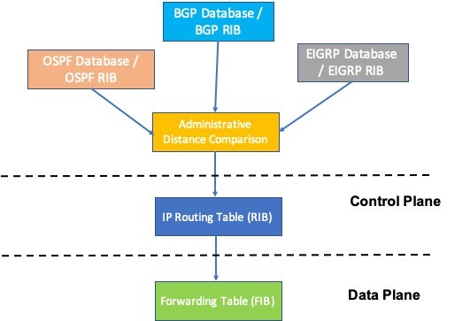
Image 2 – RIB & FIB mapping with Data Plane & Control Plane
Forwarding Mechanisms including Cisco Express Forwarding
Let us briefly discuss three different IP packet forwarding mechanisms that have been used over the years in the networking world. We will focus on the forwarding mechanisms that Cisco developed (Fast Switching and Cisco Express Forwarding ) to overcome the challenges of Native IP forwarding. The other vendors may or may not use similar mechanisms on their devices.
So, let’s jump right in.
Native IP Forwarding or Process Switching
The Native IP forwarding/Process Switching was the initial forwarding mechanism that was used by routing devices to forward the IP packets. The key features/steps of this method are described below. Here we are considering that the IP packet received by a router needs to be sent to a destination that is not directly connected to the current router.
Steps for Native IP Forwarding
- When a routing device receives a frame, the Frame Check Sequence (FCS) in the frame trailer is verified. FCS is used to determine if the received frame is erroneous or not. In case FCS fails, the frame is discarded.
- The source and destination MAC are checked from the L2 header of the frame received. The destination MAC address should be the same as that of the input interface of the router.
- The Layer 2 header is removed once point 2 is verified.
- L3 IP Header checksum is verified for the packet. If the checksum is verified and successful, further processing is done, or else the packet is dropped.
- Source and Destination IP lookup is performed.
- TTL lookup is also performed. If the TTL value is 1 or less, the packet is dropped.
- RIB lookup is performed against the destination IP and based on the largest prefix value. The next-hop IP Address and exit interface information are fetched.
- A new L2 header needs to be constructed to the packet to be forwarded. For this MAC or ARP table is referenced and relevant MAC information is gathered. If the MAC information is not available, an ARP request will be sent.
- The TTL value is reduced by 1 and the new checksum value is calculated. Both values are attached to the L3 header.
- The new L2 header (with MAC addresses fetched from MAC or ARP table) is constructed with new FCS value in the L2 trailer. The frame then will be forwarded to the next hop.
These steps were performed at every routing node between source and destination leading to high switching times.
IP Fast Switching
IP Fast Switching was introduced by Cisco to overcome the time-consuming Process Switching. The majority of the time was consumed when L2 and L3 lookups were performed and a new L2 header was created in case of Process switching. The lookups for the next-hop IP address, exit interface, and L2 information are primarily required to forward the IP packet.
What happened in Fast switching was that when the first packet to a destination was received by a router, then the Process switching took place. The information about the next-hop, exit interface, and L2 headers that were derived from initial packet processing was then saved in a route cache (a high-speed cache) to be reused for the next packet for the same destination. This cache-based retrieval reduced the time that was otherwise used for various lookups every time the packet was received. The data from the cache was used to quickly construct the L2 headers, attach them to the packet, and forward it to the next hop.
Disadvantages of Fast Switching
- It relied on the cache that kept building up as more prefixes were added. Memory issues were seen on the routing device degrading its performance.
- Process switching was required for the initial packet. This was still a challenge and not efficient.
- In case there was a change in data (like next-hop changed), the particular entry in the cache was invalidated rather than being updated. Thus, the whole mechanism of Process switching was performed for the new information.
- The cache had to be refreshed after a particular time to keep a check on space issues. In such a case, the Fast Cache was re-initialized leading to the same Process switching times.
Command in Cisco – “show ip cache” (sample output below) can be used to see Fast Switching cache.
R1#show ip cache
Prefix Length Age Interface Next Hop
3.3.3.0/24 00:00:10 FastEthernet0/0 192.168.10.1
Cisco Express Forwarding (CEF)
When we talk about Cisco Express Forwarding vs. Fast Switching, Cisco Express Forwarding (CEF) overcame the challenges of Fast switching. CEF is proprietary to Cisco devices. It is highly advanced and has high switching speeds. Most of the Cisco devices come with CEF enabled by default. If not, it can be enabled using CLI.
Instead of using RIB lookup, Cisco Express Forwarding references and creates FIB and another table called the Adjacency table. This table is sometimes called CEF table. Remember we highlighted this in the earlier section relating to FIB? FIB, in the case of Cisco Express Forwarding, contains network prefixes and next-hop IP Addresses. The Adjacency table on a router contains the information of adjacent/neighbor routers, next Hop IP Address, exit interface, and L2 header information.
When the RIB is created whether a packet is received or not, CEF comes into action and fills up the FIB with route prefixes and next-hop IP addresses based on the best route captured from the RIB. Once FIB starts getting updated, the Adjacency table also starts to fill up with information like the Next Hop IP from FIB, the exit interface on the host router to that IP that is known from the RIB, and the Layer 2 header information (MAC addresses, etc.) The Next Hop IP address acts as a key to join the FIB and Adjacency tables and the data extracted is used by the router to forward the packet.
Working of Cisco Express Forwarding
Refer to Image 3 for the network setup. We have constructed the FIB and Adjacency tables on Router A based on Image 3. Here we can see that the Destination Networks 3.0.0.0/8 and 4.0.0.0/8 can be reached by forwarding the IP packets via FastEthernet0/0 (Fa0/0) on Router A to the next-hop IP address 10.0.0.2 on Router B. Since, the next-hop IP address is same for both networks, Adjacency table contains only one entry.
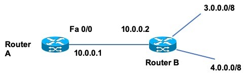
Image 3 – Cisco Express Forwarding Example
Forwarding Information Base (FIB)
| Destination Prefix | Next Hop IP Address |
| 3.0.0.0/8 | 10.0.0.2 |
| 4.0.0.0/8 | 10.0.0.2 |
Adjacency Table
| Next Hop IP Address | Exit Interface | Layer 2 information |
| 10.0.0.2 | FastEthernet 0/0 | <<Mac Address and Other information>> |
In case the next hop changes, the corresponding information will also be updated automatically in FIB and Adjacency tables.
When a packet arrives at router A, all the steps (See Native IP Forwarding in the previous section) till the Destination IP lookup and TTL verification are done. Post that, Destination IP is verified against the FIB and adjacency table (No RIB lookup) making the lookup faster than the previous 2 methods that we discussed. When all the information (L2 header information, next-hop IP, exit interface) is fetched, the TTL value is decreased by 1 and the checksum is recalculated and updated in the L3 header. Finally, the L2 header is attached and the frame created is forwarded to the next hop.
Cisco Express Forwarding can be enabled on line cards as discussed earlier in the post to reduce CPU utilization. CEF is also used as the base for the MPLS forwarding mechanism. We will talk about MPLS Routing tables in a separate post.
Cisco Express Forwarding: FAQs
Cisco Express Forwarding or CEF is a networking, or precisely forwarding mechanism in Cisco Devices that enables fast-forwarding of IP packets. It is better than native IP forwarding and IP fast switching mechanisms that produce lag in the normal IP forwarding.
Forwarding Information Base (FIB) and Adjacency table are created when CEF is enabled on a Cisco device.
CEF works by populating the FIB and the adjacency table at the time RIB is populated. As the FIB and adjacency table contains the next-hop information, exit interface, and layer 2 information, the packet does not need to perform layer 2 lookup (in MAC table) and heavy RIB lookup for the next hop. All the information is available via FIB and adjacency tables.
So, when an IP packet arrives on a router enabled with CEF, the layer 2 header is checked and removed, layer 3 information is scanned in FIB, corresponding layer 2 information is fetched from the adjacency table, and a new layer 2 header is created and attack hed to the layer 3 header (updated after recalculatingTTL and checksum), and the frame is forwarded.
RIB is a control plane routing table, while FIB is a data plane routing table. Both work in tandem for routing and forwarding IP packets. Any changes in the RIB or routing table are also reflected in FIB.
Good Reads & References
Images are subject to Copyright @The Unprecedented Cult
CURATED & WRITTEN BY
AYUSH PANDYA
(AUTHOR – THE UNPRECEDENTED CULT)
This really helped me alot, i looked for many explanations for CEF RIB FIB, this article is amazing, thank you for sharing it.
Thanks Mohamed
Very well articulately & structurally explained the difficult aspects of networking in a simple understandable to novice as well as veteran engineers. Your use of database concepts are really amused… Read more »
Thanks Zahid. Glad you liked the post.