Table of Contents
Introduction
Long-Term Evolution or LTE is a telecommunications standard and technology for wireless communications and high-speed mobile data. It is an enhanced version of 3rd Generation mobile technology with better data rates and increased capacity.

Courtesy – BetaNews
LTE introduces a new radio interface (eNodeB) and flat core architecture (EPC) for its working.
LTE is sometimes also referred to as 4G LTE.
The data rate of the LTE network is theoretically 10 times more than 3G. Downlink speeds in LTE can reach up to 300 Mbps while the uplink speeds can reach up to 75 Mbps.
In this article, we will dive into the concepts of LTE and its architecture. Here, we will also discuss the different network components of LTE and their connected interfaces that aid in the overall functioning of the technology.
Network Components of LTE
The LTE consists of two distinct network blocks:
- E-UTRAN (Evolved Universal Terrestrial Radio Access Network)
- EPC (Evolved Packet Core)
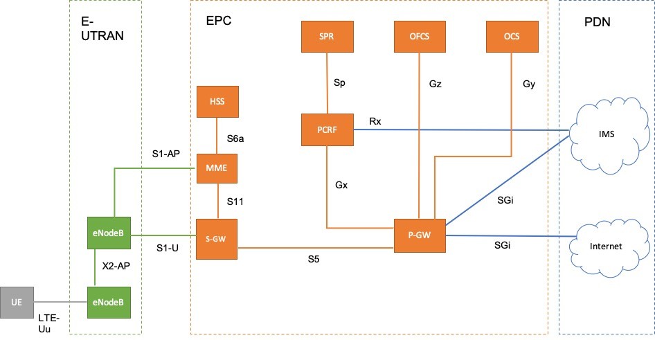
The 3rd block in the figure below shows PDN or Packet Data Network to which the LTE network connects to access the internet and other services.

E-UTRAN and EPC are together referred to as Evolved Packet System or EPS.
The UE in the image above is the User Equipment which could be a mobile phone, laptop, etc.
Evolved Universal Terrestrial Radio Access Network or E-UTRAN
The E-UTRAN relates to the LTE component that has a radio interface. This component acts as the first point of communication with the User Equipment (UE) and the source point for the communication with the Evolved Packet Core (EPC).
eNodeB
The E-UTRAN consists of Evolved Node B (eNodeB) which is an enhanced version of Node B, part of the 3G architecture. eNodeB has a radio interface and connects different types of UEs with the Evolved Packet Core as part of the LTE network.
The functions of eNodeB are as follows:
- Provides UE with a radio interface
- Radio Resource Management – release and allocation of radio resources in user and control plane
- Radio Admission Control – allows or rejects radio bearer requests
- Connection Mobility Control – radio resource management of UEs
- Radio Bearer Control – setup, maintenance, and release of radio bearers
- Inter-Cell Interference Coordination
- Connects with S-GW for forwarding user data packets
- Co-ordinates with MME for selection against a UE
- Generates route towards MME
- Performs encryption and decryption of data packets
- Header compression and decompression of data packets
- Helps in the transmission of paging messages and broadcast information via LTE-Uu interface
- Reception of paging and broadcast messages from MME
Evolved Packet Core or EPC
Evolved Packet Core is a flat system network that takes care of the forwarding of the data packets to and from the Packet Data Networks (PDNs), user authentication, mobility management, call handover, and much more.
Multiple components within the EPC have different functions which are discussed as follows:
Mobile Management Entity or MME
The Mobile Management Entity or MME is the primary control entity in LTE that handles all the signaling between the eNodeB and EPC. It also takes care of signaling between the UEs and the EPC. The MME signaling is also known as NAS (Non-Access Stratum) signaling.
The following are the functions of MME:
- Session Management and Mobility Management using NAS signaling
- User authentication and profile download via HSS over S6a interface
- Tracking of user location
- Evolved Packet System bearer management
- Paging, tracking, and handover management (handover between different eNodeBs)
- Allocation of a gateway router if more than one is available
- In case X2 is not available, MME is used for the transmission of handover messages between eNodeBs
- Generation and allocation of temporary identities to UE
- Enforcing UE roaming checks
- Ciphering of NAS signaling
- Security key management
- Control function for the mobility between LTE and 2G/3G networks
Serving Gateway or S-GW
Serving Gateway or S-GW terminates the interface towards E-UTRAN and acts as the mobility anchor for inter-eNodeBs handover and inter-3GPP handover i.e. LTE and other CS networks.
Home Subscriber Server or HSS
An HSS is a database that contains user profile-related information. HSS also contains the user subscription-related details and thus is an important entity in EPC. MME uses the information from HSS to perform user authentication. HSS is also used for mobility management, call session control, and access authorization.
Packet Data Network Gateway or P-GW
P-GW is another important element of the EPC. It acts as a gateway and is responsible for attaching a UE with the external PDN network. It can be regarded as an entry and exit point for the traffic for UE.
Some of the other functions of P-GW are:
- IP routing and forwarding
- IP address allocation for UE
- Mobility anchor between 3GPP and non-3GPP
- Policy enforcement
- Packet filtering on a user basis
- Lawful interception
- Charging support
Policy and Charging Rules Function or PCRF
PCRF is a combination of two functional elements: PDF (Policy Decision Function) and Charging Rules Function (CRF). It manages the service policy and also sends QoS setting information for each user information. It provides functionality that ensures that data flow is according to the user’s subscription profile.
PCRF also makes it easy for the non-3GPP devices to connect to the LTE network. PCRF feeds QoS information to the P-GW and hence takes care of LTE quality requirements.
Subscriber Profile Repository or SPR
SPR is a logical database that provides subscription information to the PCRF. Further, it provides QoS and charging-related information, user allowed services, and more. SPR also stores dynamic business rules required for PCC (Policy and Charging Control). It contrasts with HSS that stores static user subscription-related data.
Offline Charging System or OFCS
In OFCS, CDF (Charging Data Function) receives the charging events and generates the CDRs. CDF, transmits the generated CDRs to CGF (Charging Gateway Function). CGF further forwards CDRs to the Billing domain.
Online Charging System or OCS
In OCS, OCF (Online Charging Function) receives the charging events and decides the usage of resources based on Rating Function (RF) and Account Balance Management Function (ABMF).
Interfaces in LTE
UE-eNodeB
LTE-Uu
The interface connects eNodeB with the UE and promotes data transfer. LTE-Uu is also known as the LTE radio interface. The functions and protocols for the working of the interface are implemented in the eNodeB. The interface caters to both control and user plane functionality.
The control plane connections over LTE-Uu are the RRC connections while the user plane connections are the logical channels, part of Data Radio Bearers (DRBs).
eNodeB – eNodeB
X2
The interface works between two eNodeBs. X2-AP protocol is used in the control plane while GTP-U is used in the user data plane. All the eNodeB handovers are performed over X2 via X2-AP protocol.
eNodeB-MME
S1-AP
It is the control plane interface between eNodeB and MME. The signaling messages are transmitted by S1-AP through Stream Control Transmission Protocol (SCTP).
eNodeB-SGw
S1-U
S1-U is the user data plane interface between the eNodeB and S-GW. It uses the GTP-U protocol. The GPRS tunneling protocol user plane (GTP-U) provides tunneling for user plane bearers.
MME-SGw
S11
A control plane interface between MME and S-GW. It uses the GTP-C protocol for signaling messages between MME and S-GW. The interface is also used for co-ordination to establish SAE bearers in EPC.
MME-HSS
S6a
S6a is a control plane interface between MME and HSS. The user subscription and also the user authentication details are exchanged via this interface. The interface uses the Diameter protocol for functioning.
SGw-PGw
S5
A control and data plane interface between S-GW and P-GW. The interface establishes a GTP tunnel (GTP-U) per bearer in the user plane and GTP tunnel (GTP-C) management per user in the control plane.
SPR-PCRF
Sp
A control plane interface between SPR and PCRF. The interface works on the Diameter protocol.
PCRF-PGw
Gx
Gx is a control plane interface between PCRF and P-GW. The policy control and charging rules are transferred from PCRF to P-GW via this interface. This helps in implementing QoS policy and charging control.
The interface uses the Diameter protocol for its functioning.
OCS-PGw
Gy
A control plane interface between OCS and P-GW that uses Diameter protocol.
OFCS-PGw
Gz
Gz is a control plane interface between OFCS and P-GW, and it uses GPRS Tunneling Protocol.
PGw-PDN
SGi
A control and data plane IP interface between P-GW and PDN. The data plane uses IP forwarding protocols, while the control plane makes use of RADIUS/Diameter protocol.
Conclusion
This wraps up the post. Most of the MNOs (Mobile Network Operators) today have already migrated to LTE, though VoLTE (Voice over LTE) is still not prevalent everywhere. Initially, LTE and 4G were given to be separate technologies, but over the years the terms have been used interchangeably due to the practical speeds and capacity of both technologies.
In this article, we discussed, in brief, all the different components as part of the LTE architecture and also went through which interfaces and protocols work in between those network components. LTE itself is a huge topic and requires extensive knowledge. In the days to come, we will try and publish more information related to LTE. Stay tuned!
CURATED & WRITTEN BY
AYUSH PANDYA
(AUTHOR – THE UNPRECEDENTED CULT)