Table of Contents
Local Area Network (LAN) has been a part of the networking world since its inception. In a couple of our earlier posts, we went deep into the concepts of L3VPN and how it works. We gained insights about VRF, MP-BGP, Route Target (RT), Route Distinguisher (RD), and how they all combine to create a full-grade L3VPN solution for a customer. L2VPN is another popular service that is deployed by enterprises in collaboration with Service Providers for the interconnection of their distributed sites.
In this post, we will talk about L2VPN and its various modes. As we have been focusing on the MPLS related technologies, we will restrict our discussion to the L2VPN deployment with the MPLS core.
What is L2VPN?
L2VPN is a layer 2 service where different locations (customer sites) of an enterprise interconnect to form a big LAN segment. All the locations can exchange layer 2 data with each other via this Virtual LAN in a private and secured way.
L2VPN and L3VPN, the difference?
L3VPN works at the IP or Layer 3 of the OSI model. This means that L3VPN uses IP related information for its functioning. An identifier, Virtual Routing and Forwarding (VRF), is created and attached to an IP interface. This VRF identifies a unique customer in L3VPN. The L3VPN data is transported across the MPLS core using two labels, VPN Label and Transport (MPLS) Label. The Transport Label is crucial for data forwarding within an MPLS network, while VPN (VRF) Label uniquely identifies a customer.
When a data packet reaches the remote end (or remote Provider Edge (PE) node) of the MPLS network, the transport label is stripped off and the VPN label is then looked up against the VRF data for that customer. The data packet is then routed accordingly to the remote CE.
The VRF data contains all IP related routes that are captured via routing protocols between PE and CE. VPN labels are attached to these IP routes as per the configuration. So, when the VPN label is looked up, the IP information is compared and the data packet is forwarded to the concerned interface of the PE, from where it reaches the CE. Thus, Service Provider (SP) needs to take care of the routing protocols and the relevant configuration on the nodes. In brief, there is a dependency of the Service Provider (SP) for transporting L3VPN data across the MPLS core.
L2VPN, as the name suggests is an E2E Layer 2 service. The data frames are forwarded based on the Layer 2 information (MAC, VLAN ID, VCI, etc.). The Service Provider (SP) is not required to take care of the routes from CE, the topology of the customer network, and routing. An interesting thing to note is that in the VPLS model of L2VPN, the VPLS labels and Layer 2 information are distributed among the nodes via Data Plane and Control Plane, while in L3VPN, the routes and VPN labels are distributed among the nodes via MP-BGP that works in the Control Plane.
L2VPN Models
The L2VPN is divided into two models or types. One is based on the MPLS core network and the other is based on the IP core.
The figure below shows the two models and their sub-divisions. As stated earlier, we will keep our discussion restricted to the MPLS Core in this post.
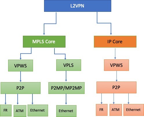
The MPLS Core-based model has two broad divisions: Virtual Private Wire Service (VPWS) and Virtual Private LAN Service (VPLS). We will discuss both these services in the coming sections.
An interesting fact to know is that in MPLS core-based L2VPN, there is no explicit requirement to change the Service Provider’s infrastructure. The L2VPN services can run over the existing MPLS core with minimal configuration. This converts to an opportunity for the Service Providers to deploy a new service over the existing infrastructure. As all the routing is done at the customer end, the MPLS network helps only in forwarding the L2 data.
Virtual Private Wire Service (VPWS)
Virtual Private Wire Service or VPWS is a Point-to-Point (P2P) service implementation of L2VPN. It provides layer 2 data flow of the same or different types (FR, ATM, etc.) of L2 services over the MPLS core attaching the two customer sites.
Terms in VPWS
Two terms hold significance in VPWS, Pseudo Wire (PW) and Attachment Circuit (AC).
What is Pseudo Wire (PW)?
In VPWS, there is a concept of virtual connection or Pseudo Wire.
A Pseudo Wire is a logical connection between the two Provider Edge (PE) nodes that connect two attachment circuits or Pseudo Wire End Services (PWES).
PWES can be either of the following services used between the PE and CE nodes:
- Ethernet, VLAN, or 802.1Q tunneling (QinQ)
- ATM VC or VP
- Frame Relay VC
- HDLC
- PPP
What is an Attachment Circuit?
An attachment circuit is a layer 2 connection between the Provider Edge node in the MPLS/Backbone/PSN network and the Customer Edge node (CE). This connection may be of different types: ATM, Frame Relay, Ethernet, etc. The two ends of a Pseudo Wire are connected to the CEs via attachment circuits.
The connection in an attachment circuit may be physical or virtual.
There are few modes in the Attachment Circuit:
Port Mode – Untagged Ethernet Packets are sent/received over the circuit.
802.1Q VLAN (Trunk Mode) – Only tagged Ethernet VLAN packets are sent/received. The interface is configured in trunk mode.
Dot1q tunnel mode – Tagged or Untagged packets can be sent in a tunnel between two PEs. An access VLAN tag is added to the packet.
The Working
In VPWS, as stated above, the services deployed over PW may be ATM, Ethernet, Frame Relay, etc. Because we are focusing on the MPLS model of L2VPN, the transport medium is the MPLS core network of the Service Provider.
The frames received on the attachment circuit are encapsulated and sent across the Pseudo Wire to the remote PE. In our case, the Pseudo Wire works in the MPLS core network. When the frames are received on the remote PE, the added encapsulation is removed and the frame is forwarded to the relevant attachment circuit.
As part of the encapsulation, two labels are added to the frame: Transport/Tunnel Label and Virtual Circuit (VC) Label.
The transport label is used in forwarding the L2 frames over the MPLS network. This label is may be allocated using the RSVP-TE/targeted LDP/BGP etc. The working of the transport label is the same as in the MPLS network. The Packet Switched Network (PSN) tunnel between the two PE nodes is a Label Switched Path (LSP), the same as in MPLS.
Each Pseudo Wire is tied to a PW or VC (Virtual Circuit) label that uniquely identifies a Pseudo Wire. This holds relevance, where multiple Pseudo Wires are multiplexed on a Packet Switched network tunnel (PSN tunnel). It is using this label that the remote PE identifies the relevant attachment circuit or Pseudo Wire.
VC Label is also sometimes referred to as VC ID (Virtual Circuit ID).
VC ID is an ID that matches on all PE for the same LAN segment. Virtual Circuit ID is configured on each interface and uniquely identifies a Layer 2 circuit among all the Layer 2 circuits to a specific neighbor. The key to identifying a particular Layer 2 circuit on a PE router is the neighbor address and the VC ID.
An optional Layer 2 Encapsulation is also available in VPWS other than the two labels discussed. It is also called Emulated VC Encapsulation. The Emulated VC Encapsulation is a 32-bit control word that contains information about the enclosed L2 PDU. The data frames are thus encapsulated with VC label, Transport label, and Layer 2 Encapsulation (optional) on top of the Layer 2 header. The VC label is the inner label while the transport label is the outer label. This is because a transport label is needed for the forwarding of data packets within an MPLS network.
Layer 2 Encapsulation also takes care of frame sequencing.
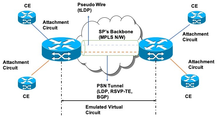
The PSN tunnel provides the actual path (LSP) for the Pseudo Wire. The L2 traffic is invisible to the MPLS core network which means that the MPLS network is invisible to the customer edge devices. In other words, there is no specific role of the MPLS network in VPWS except for forwarding the L2 data.
Use of targeted LDP or tLDP?
A targeted LDP or targeted label distribution protocol is a type of LDP that is specifically used to create an LDP session between the non-directly connected devices.
- Pseudo Wire is signaled via tLDP session between the PE routers.
- A tLDP session helps in advertising the VC label that is associated with a Pseudo Wire.
- The VC label is advertised in a label mapping message using a particular advertisement mode. In the Downstream Unsolicited (DU) mode, the VC label is advertised by the egress PE to ingress PE for the AC over the tLDP session.
- Tunnel or Transport label for MPLS functionality can be advertised via two modes i.e. Downstream Unsolicited or Downstream on Demand. This is achieved by enabling basic LDP. The other protocols like RSVP-TE, BGP, etc. can also be used for transport label mapping.
The Pseudo Wire Technologies
In VPWS, two pseudo-wire technologies enable point-to-point Layer 2 services:
- Any Transport over MPLS (AToM)– A Pseudo Wire technology that uses an MPLS-enabled network to provide different Layer 2 services. AToM was developed by Cisco. The working of VPWS that is discussed in the above sections is related to AToM.
- L2TPv3 – Layer 2 Tunneling Protocol version 3. A pseudo-wire technology for purely native IP-based networks.
Both AToM and L2TPv3 support the transport of Frame Relay, ATM, High-Level Data Link Control (HDLC), PPP, and Ethernet traffic over the MPLS or IP core.
Virtual Private LAN Service (VPLS)
Virtual Private LAN Service or VPLS, is a Point-to-Multipoint (P2MP) and Multipoint-to-Multipoint (MP2MP) L2VPN service. VPLS is designed for applications that require multipoint access across geographically distributed locations.
Using VPLS, several customer sites (or distributed Ethernet LANs) can be interconnected to work as a single bridged domain over the MPLS network. In simple terms, VPLS uses the Layer 2 architecture to create multipoint VPNs that connect several sites over a Wide Area Network (WAN) or Metropolitan Area Network (MAN). The different customer sites are connected via the Service Provider’s MPLS core network.
For enterprises, the Service Provider’s MPLS core network seems like a big Ethernet LAN.
VPLS vs MPLS?
MPLS is a broad service that is deployed over the traditional IP network for enhanced forwarding of IP packets. VPLS on the other hand is a Layer 2 service that makes use of the MPLS network to deploy the respective L2VPN business.
Terms in VPLS
What is a Bridge Domain?
A bridge domain refers to the broadcast domain consisting of a set of interfaces (physical and virtual). The operations within the bridge domain are the same as in an ethernet bridge. The data frames that are part of a bridged domain are switched as per the specific destination MAC address.
All kinds of frames (Multicast, Broadcast, etc.) can flood the bridge domain. The source MAC address is also learned for all the incoming frames in a bridge domain.
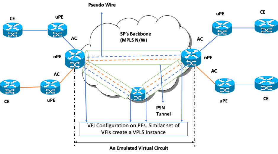
The Attachment Circuits are the same as we discussed in VPWS. They are tied to the bridge domain and are a set of physical, or virtual, or mixed ports that connect uPE and nPE.
What are nPE and uPE?
A network Provider Edge (nPE) is an edge node on the SP’s backbone (MPLS core network). It holds all the VPLS forwarding MAC tables and bridge domain information
A user-facing Provider Edge (uPE) is a node in between the CE and nPE. uPE is a node used for Layer 2 data aggregation.
What is VFI?
A Virtual Forwarding Instance or VFI is a virtual bridge port that can perform the native bridging functions like forwarding based on destination MAC, Source MAC learning, etc. The VFI is generally configured on the nPE node and is associated with a VPLS instance. The nPE node makes forwarding decisions based on the VFI value. Once the VFI is defined, it needs to be attached with the Attachment Circuit.
VFI specifies the VPN ID of a VPLS domain, type of tunnel signaling and encapsulation, and the addresses of other PE devices in the domain.
VPN ID uniquely identifies a VPLS instance.
What is a VPLS instance?
A set of VFIs formed by the interconnection of Emulated Virtual Circuits is called the VPLS instance. VPLS instance is the logical bridge over the Packet Switched Network (PSN).
What is VSI?
A VFI connected to a bridge domain forms a Virtual Switching Instance (VSI). It provides Ethernet multipoint bridging over a PW mesh. A VSI learns remote MAC addresses and is also responsible for proper forwarding of the customer packets to the concerned destination nodes and loop-free VPLS domain.
MAC address learning and initial label distribution
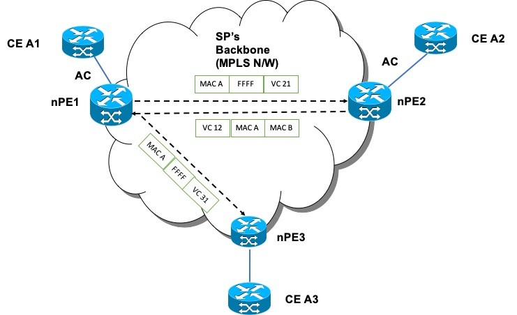
The nodes nPE1 and nPE2 are connected via tunnel. nPE1 assigns a label VC 12 for its AC and nPE2 assigns VC 21. These two labels are exchanged between the two nodes via the tunnel.
When a packet from CE A1 (customer A) destined for CE A2 reaches nPE1, it does not know the MAC address of CE A2. Because of this, a broadcast message is sent which is propagated from nPE 1 to nPE 2 and nPE3. The message contains source MAC address as MAC A and destination MAC as FFFF (generic MAC in broadcast message). The message is also attached with labels VC 21 and VC 31 it learned from nPE2 and nPE3 respectively.
When nPE2 receives the broadcast message, it replaces the generic MAC with the MAC of CE A2 and also associates VC 21 with MAC A denoting MAC A is behind nPE1 (a nPE1 and nPE2 had already shared the VC labels initially). Similar process happens for packet from CE A2 to CE A1, CE A1 to CE A3, and CE A3 to CE A1.
The Working
There are two ways of VPLS functioning:
- VPLS Auto Discovery via BGP and Signalling via tLDP
- VPLS Auto Discovery and Signalling via BGP
VPLS Auto Discovery via BGP and Signalling via tLDP
BGP Auto Discovery
The VPLS auto discovery is an important component of the VPLS functioning. The auto discovery removes any dependency of manually configuring the nodes part of the same VPN. Using auto discovery, any new nodes with a specific VPN are added automatically to the mesh of existing nodes with the same VPN. In other words, if a node is added to a specific VPN, then all the existing nodes in the VPN are signaled for the addition of a new member.
The VPLS auto discovery uses BGP extended communities to identify members of a VPLS instance. To be precise, the Route Target community is used for the same. As VPLS instance is a mesh of virtual circuits and VFIs, a single Route Target suffices for the discovery. So, the Route Target is the identifier of the VPLS instance.
In the case of the MPLS backbone, a nPE via iBGP announces that it belongs to a specific VPLS instance by annotating its NLRI with Route Target. It also accepts the NLRIs from the nPEs with the same Route Target. If the nPE is to no more take part in the VPLS, it withdraws the NLRIs with the Route Target it used during the discovery.
VPLS signalling via tLDP
The setting up and tearing down of Pseudo Wire is called signaling.
tLDP helps in setting up the Pseudo Wire, and also creating and distributing the VC label or VPN label to identify a specific VPLS instance. The local VC labels are created and the two edge routers of the PW send their local labels to each other.
When a traffic from the Attachment Circuit is sent to the connected nPE for a remote site, the nPE does not know the MAC of the remote site. A broadcast request from the source nPE to all the nPEs is sent with the Source MAC address of the source router and VPN label value advertised by the remote nPE.
Once the remote nPE receives the broadcast message, it dumps the data of Source MAC against the VPN label in its database. This allows the remote router to understand which network is behind the source nPE. Once the data is dumped, the remote nPE sends back the response with its MAC address. Once the MAC addresses are in place, the layer 2 data is easily transported across the Service Provider’s backbone (or MPLS network).
VPLS Auto Discovery and Signaling via BGP
The other signaling method is BGP. With this, BGP takes care of both discovery and signaling. The iBGP peers exchange the UPDATE messages with L2VPN information to perform both discovery and signaling.
The BGP discovery mechanism is the same as discussed above.
VPLS signaling via BGP
The important factor in VPLS signaling via BGP is Network Layer Reachability Information (NLRI). The BGP Network Layer Reachability Information consists of Route Distinguisher (RD), VPLS Endpoint (VE ID), VE Block Offset (VBO), VE Block Size (VBS), and Label Base (LB). The BGP extended community attributes carry next-hop value, RT value, and any other layer 2 information.
The Route Target import/export mechanism as used in L3VPN is also used here to filter out the L2 VPN NLRI information for a particular VPLS instance. The Route Distinguisher (RD) keeps the NLRI unique for various VPLS instances.
In BGP signaling, the nPE (site) which has a unique VE ID within a VPLS instance sends a block of VC labels as part of the NLRI. The NLRI also contains VE ID and RD that identifies VPLS specific NLRI for an nPE. The nPE sends the label block to remote nPEs of the same VPLS instance. The label block created (via BGP) and chosen by source nPE is tagged against the VE ID of the remote nPE. Thus, when the NLRI reaches the remote nPE, it knows that a specific label block is meant for it.
The Label Base (LB) is the label number of the starting label. VBS is the block size of the number of labels in a single block. It also identifies the number of PWs that can be created in a block. VBO identifies the label block from which a label value is selected to create a PW. If VE IDs are still left, fresh NLRI is generated to assign labels for the nPE’s left.
There is a formula to identify if an nPE will accept the NLRI from a remote nPE.
VBO <= W < VBO + VBS -> where W is the VE ID of the remote nPE that gets NLRI from the source nPE. If the condition is true, the remote PE with VE ID accepts the NLRI information. The VPLS label is generated and PW is signaled between source and remote nPE.
The BGP attaches the “Layer 2 Info Extended Community” which is used to signal control information for the creation of PWs.
The VPLS packets are forwarded from one nPE to remote nPE using MAC address learning of the customers attached to an nPE. Any packet that comes from CE is dumped in the FIB table with MAC address and port.
When a frame is received on an nPE with a destination not in its FIB, a broadcast message is sent to every other port in the VPLS instance. The relevant nPE then sends the MAC information to the source nPE that dumps the data in its FIB.
Sample L2VPN Command
Router# show mpls l2transport vc
Local intf Local circuit Dest address VC ID Status
————- ——————— ————— ——— ———-
Et0/0 Ethernet 192.168.1.102 100 DOWN
Local Interface (Local intf) is the interface on PE facing the CE or part of the AC. The destination address (Dest address) is remote PE IP. VC ID is the VC identifier/label for a particular PE, interface, and PW. VC ID should be the same on the routers having the same AC and PW.
L2VPN FAQs
L2VPN is a layer 2 service where different locations (customer sites) of an enterprise interconnect to form a big LAN segment.
There are L2VPN models – one based on MPLS Core and the other on the native IP network.
The two services are – Virtual Private Wire Service (VPWS) and Virtual Private LAN Service (VPLS).
A Pseudo Wire is a logical connection between the two Provider Edge (PE) nodes that connect two attachment circuits or Pseudo Wire End Services (PWES).
An attachment circuit is a layer 2 connection between the Provider Edge node in the MPLS/Backbone/PSN network and the Customer Edge node (CE).
A Virtual Forwarding Instance or VFI is a virtual bridge port that can perform the native bridging functions like forwarding based on destination MAC, Source MAC learning, etc.
A VFI connected to a bridge domain forms a Virtual Switching Instance (VSI).
A bridge domain refers to the broadcast domain consisting of a set of interfaces (physical and virtual). The data frames that are part of a bridged domain are switched as per the specific destination MAC address.
The command is – show mpls l2transport vc
L2VPN is a broad term in the service provider’s domain that essentially works on the concept of Layer 2 functionality. VPLS is a part of the L2VPN MPLS core-related model.
L2VPN works on the layer 2 architecture while L3VPN works on the layer 3 architecture. In simple words, L2VPN works on MAC addressing while L3VPN works on IP.
VPLS is a Layer 2 VPN service that is deployed over the MPLS network to form an L2VPN network. MPLS is a broad service that is deployed over the IP network for fast forwarding of IP packets.
Good Reads and References
CURATED & WRITTEN BY
AYUSH PANDYA
(AUTHOR- THE UNPRECEDENTED CULT)
Great blog post!